

Arduino Eelectronic Component Tester project is one of the most useful tools you can build for an electronics workbench. With a single Arduino Nano, three test terminals and an OLED display, this tester can automatically identify many commonly used components and display their values, type and pin configuration.
Unlike a basic continuity tester, this project performs several controlled electrical tests on the connected component. The firmware checks all possible terminal combinations, repeats the measurement three times, rejects unstable readings and displays a median result only when the measurements agree.
This guide explains the complete circuit, component connections, working principle, firmware configuration, assembly process, calibration procedure and safe operating method according to the supplied firmware. The code is designed for an ATmega328P-based Arduino Nano and an SSD1306 128×64 I2C OLED.
What Is an Electronic Component Tester?
An electronic component tester is a microcontroller-based measuring device that automatically detects the type and pin arrangement of an unpowered electronic component.
Depending on the detected part, this tester can display:
- Resistance
- Capacitance
- Inductance
- Capacitor ESR
- Capacitor loss
- Diode forward voltage
- Diode junction capacitance
- BJT transistor type
- Transistor pinout
- Transistor current gain or hFE
- Base-emitter voltage
- MOSFET or JFET type
- MOSFET gate threshold voltage
- MOSFET gate capacitance
- Thyristor pinout
- Triac pinout
The original AVR transistor-tester concept was developed by Markus Frejek and subsequently expanded by Karl-Heinz Kübbeler and other contributors. Later versions became capable of testing more than transistors, which is why the device is now commonly called a component tester.
Circuit Diagram
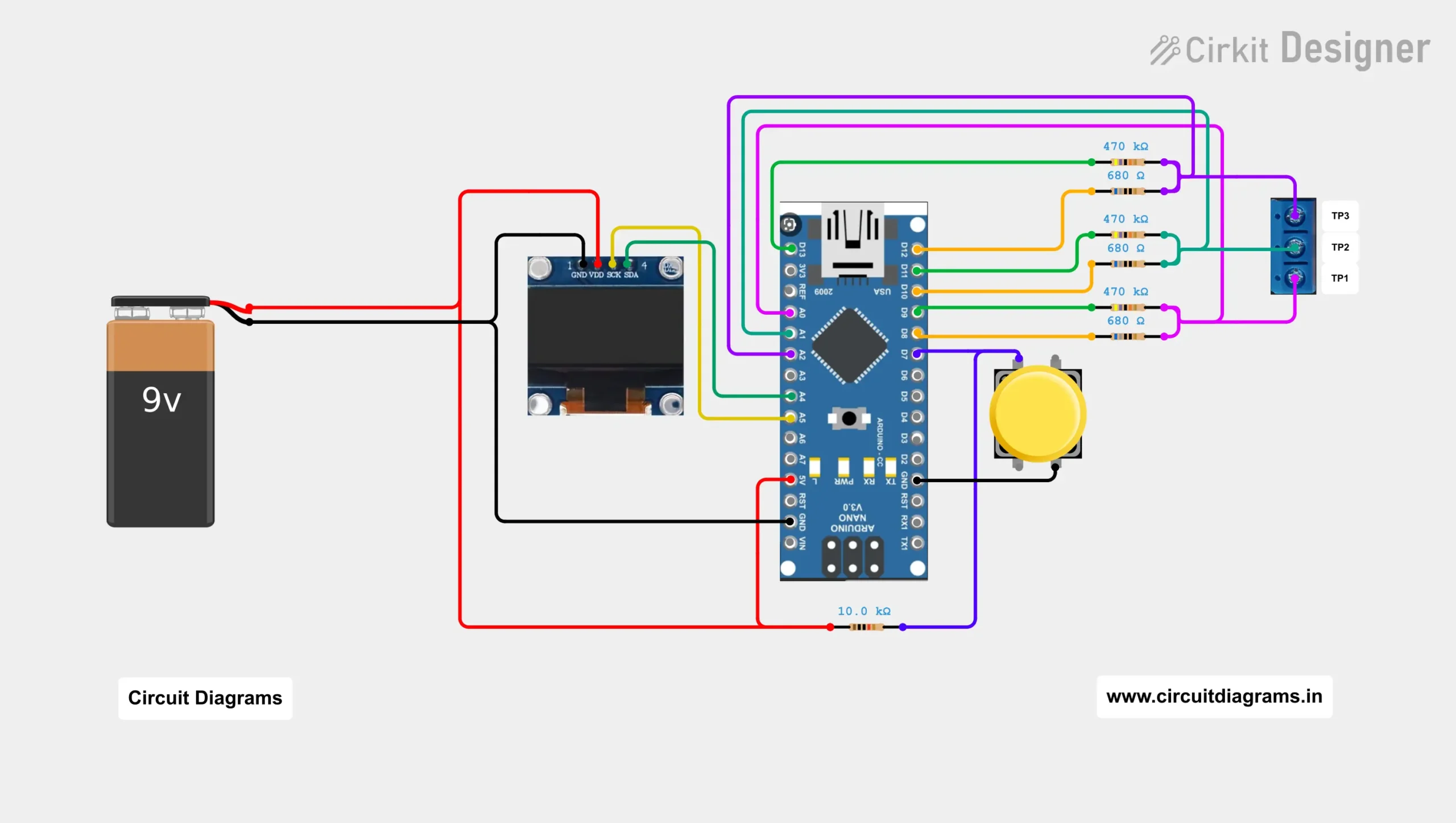
Components Required
| Component | Quantity | Recommended specification |
|---|---|---|
| Arduino Nano | 1 | ATmega328P, 5V, 16MHz |
| OLED display | 1 | 0.96-inch, 128×64, SSD1306, I2C |
| Low-range resistors | 3 | 680Ω, 1% or better |
| High-range resistors | 3 | 470kΩ, 1% or better |
| Push button | 1 | Normally open |
| Pull-up resistor | 1 | 10kΩ |
| Voltage regulator | 1 | 7805 or L7805, 5V |
| Input capacitor | 1 | 100µF electrolytic |
| Output capacitor | 1 | 47µF electrolytic |
| Bypass capacitor | 1 | 0.1µF ceramic |
| Three-pin terminal | 1 | TP1, TP2 and TP3 |
| Two-pin terminal | 1 | Battery or supply input |
| Female header strips | As needed | For removable Nano and OLED |
| Double-sided veroboard | 1 | Suitable project size |
| Power switch | 1 | SPST |
| Battery | 1 | 9V battery or suitable DC source |
| Connecting Wire | As needed | Short insulated wire |
| Enclosure | Optional | Plastic project box |
For the most accurate resistance and capacitance measurements, use precision resistors and enter their individually measured values into the firmware.
FSCircuits – Your Trusted PCBA Partner

If you’re looking for a reliable and high-quality Printed Circuit Board Assembly (PCBA) service, look no further than FSCircuits. Whether you’re a hobbyist, startup, or large-scale manufacturer, FSCircuits provides end-to-end solutions tailored to your project needs. From rapid prototyping to mass production, they offer:
- Precision SMT & THT Assembly
- Quick Turnaround Times
- 100% Functional Testing
- Low MOQ Support
- Competitive Pricing
Their expert engineering team ensures component sourcing, DFM analysis, and quality assurance at every step. With FSCircuits, you get more than just a service — you get a partner committed to your innovation.
👉 Visit fscircuits.com to get an instant quote and bring your circuit to life!
How Does This Arduino Component Tester Work?
The Arduino applies different voltage and resistance combinations to three test terminals. It then measures the resulting voltages with the ATmega328P ADC. By comparing conduction direction, voltage drop, charging time and current-related values, the firmware identifies the connected component, calculates its parameters and determines its pinout.
The ATmega328P includes a 10-bit analog-to-digital converter and configurable bidirectional I/O ports. These features allow each test terminal to be driven high, driven low or left in a high-impedance input state during the identification process.
Main Features of This Electronic Component Tester
This firmware provides several improvements over a simple one-pass Arduino tester:
| Feature | Function |
|---|---|
| Automatic component identification | Detects the component without requiring a manual mode selection |
| Automatic pinout detection | Finds the connected terminal arrangement |
| Three measurement passes | Measures the component three separate times |
| Identification comparison | Rejects the result if the detected component or pinout changes |
| Stability checking | Rejects measurements exceeding the selected variation limit |
| Median filtering | Uses the middle value of three accepted measurements |
| Charged-component detection | Checks the probe voltage before testing |
| Automatic discharge | Attempts to discharge low-voltage capacitors safely |
| EEPROM calibration | Retains calibration values after power removal |
| CRC-protected settings | Rejects invalid or corrupted EEPROM calibration data |
| OLED display | Shows results on a compact 128×64 SSD1306 screen |
| Interactive calibration menu | Adjusts all six test resistors and zero offsets |
The default stability tolerance is 3%, and it can be adjusted between 2% and 10%. Results remain visible for approximately 15 seconds before the tester returns to its idle screen.
Components the Tester Can Identify
Resistors
The tester determines the connected test-pin pair and displays the resistance. It can also identify certain three-terminal resistor networks.
For a single resistor-like component, the firmware may additionally perform an inductance measurement. This is useful when testing coils or low-resistance inductors.
Capacitors
For capacitors, the tester can display:
- Capacitance
- Connected test pins
- Equivalent series resistance
- Dielectric loss value
Small parasitic capacitances are compensated using the open-probe zero calibration.
Diodes and LEDs
The tester identifies diode polarity and displays:
- Anode terminal
- Cathode terminal
- Forward voltage
- Junction capacitance
Multiple diode junctions may also be detected. LEDs that conduct within the tester’s available voltage and current range are normally identified as diodes, although high-forward-voltage LEDs may not produce a reliable result.
BJT Transistors
The firmware distinguishes between NPN and PNP bipolar transistors and displays:
- Emitter
- Base
- Collector
- hFE or DC current gain
- Base-emitter voltage
MOSFETs and JFETs
The tester supports N-channel and P-channel field-effect devices. Depending on the detected mode, it can display:
- Source
- Gate
- Drain
- Enhancement or depletion mode
- Gate threshold voltage
- Gate-source capacitance
- Drain current
- Gate-source test voltage
Thyristors and Triacs
For a thyristor, the tester identifies the cathode, gate and anode.
For a triac, it identifies MT1, gate and MT2. The current firmware reports the device and pinout but does not show an additional numeric parameter for these two component types.
These result formats are defined directly in the supplied firmware’s component-display function.
How the Measurement Circuit Works?
Each of the three test terminals has three important connections:
- A direct analog connection to the Arduino
- A connection through a nominal 680Ω low-range resistor
- A connection through a nominal 470kΩ high-range resistor
The direct analog connections are A0, A1 and A2. The six resistor-control lines use digital pins D8 through D13.
The Arduino changes these pins between input and output states. It can therefore:
- Pull a terminal toward 5V through 680Ω
- Pull a terminal toward ground through 680Ω
- Pull a terminal toward 5V through 470kΩ
- Pull a terminal toward ground through 470kΩ
- Drive a terminal directly where required by the test routine
- Leave a terminal in a high-impedance measurement state
- Measure the voltage at the terminal
Arduino’s port mapping identifies digital pins D8–D13 as Port B, which matches the firmware’s use of the lower six Port B bits for RL1, RH1, RL2, RH2, RL3 and RH3.
Why Are Both 680Ω and 470kΩ Resistors Used?
The two resistor ranges allow the tester to work with components having very different impedances.
The 680Ω resistors provide a stronger test current for:
- Low and medium resistance measurements
- Semiconductor junction testing
- ESR measurement
- Transistor testing
- Inductance-related tests
The 470kΩ resistors provide a much smaller current for:
- High resistance measurements
- Capacitor charging-time measurements
- MOSFET gate tests
- High-impedance semiconductor checks
The original TransistorTester documentation describes separate resistance-measurement methods using the 680Ω and 470kΩ precision resistors.
Why the Tester Takes Three Measurements?
Many basic component testers display the result from a single test cycle. This firmware instead takes three complete measurement snapshots.
After the three passes, the software checks two conditions.
First, all three passes must identify the same:
- Component category
- Component mode
- Diode count
- Resistor count
- Pin arrangement
Second, the measured numerical values must remain within the configured stability percentage.
If either test fails, the OLED displays an unstable-contact warning and rejects all three readings. When the results are stable, the firmware calculates the median numerical values and displays the accepted result.
This method helps reduce the effect of:
- Loose component leads
- Oxidized terminals
- Probe movement
- Electrical noise
- ADC fluctuation
- Poor solder joints
- Human contact with the probes
OLED Memory Optimization
The project uses this U8g2 constructor:
U8G2_SSD1306_128X64_NONAME_1_HW_I2C oled(
    U8G2_R0,
    U8X8_PIN_NONE
);The _1_ section selects a paged display buffer rather than a full-screen buffer. U8g2 constructors specify the display controller, communication method and buffer configuration.
A full 128×64 monochrome frame requires 1,024 bytes. The classic Arduino Nano has only 2KB of SRAM, so allocating half of the available memory to the OLED would leave too little space for the firmware’s three measurement snapshots, variables and calibration data. The page-buffer approach reduces SRAM usage while retaining the full display resolution.
Complete Arduino Nano Pin Connections
Test Terminal Connections
| Test terminal | Direct ADC connection | 680Ω connection | 470kΩ connection |
|---|---|---|---|
| TP1 | Arduino A0 | D8 → 680Ω → TP1 | D9 → 470kΩ → TP1 |
| TP2 | Arduino A1 | D10 → 680Ω → TP2 | D11 → 470kΩ → TP2 |
| TP3 | Arduino A2 | D12 → 680Ω → TP3 | D13 → 470kΩ → TP3 |
This mapping follows the firmware definitions:
- TP1, TP2 and TP3 are Port C bits 0, 1 and 2
- RL1 and RH1 are Port B bits 0 and 1
- RL2 and RH2 are Port B bits 2 and 3
- RL3 and RH3 are Port B bits 4 and 5
On the Arduino Nano, A0–A2 correspond to these ADC inputs, while Port B bits 0–5 correspond to D8–D13.
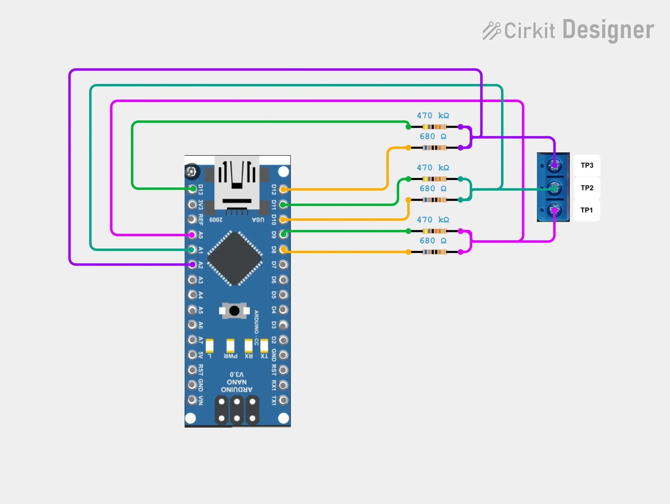
OLED Connections
| OLED pin | Arduino Nano |
|---|---|
| VCC | 5V |
| GND | GND |
| SDA | A4 |
| SCL | A5 |
The standard I2C pins on the classic Arduino Nano are A4 for SDA and A5 for SCL.
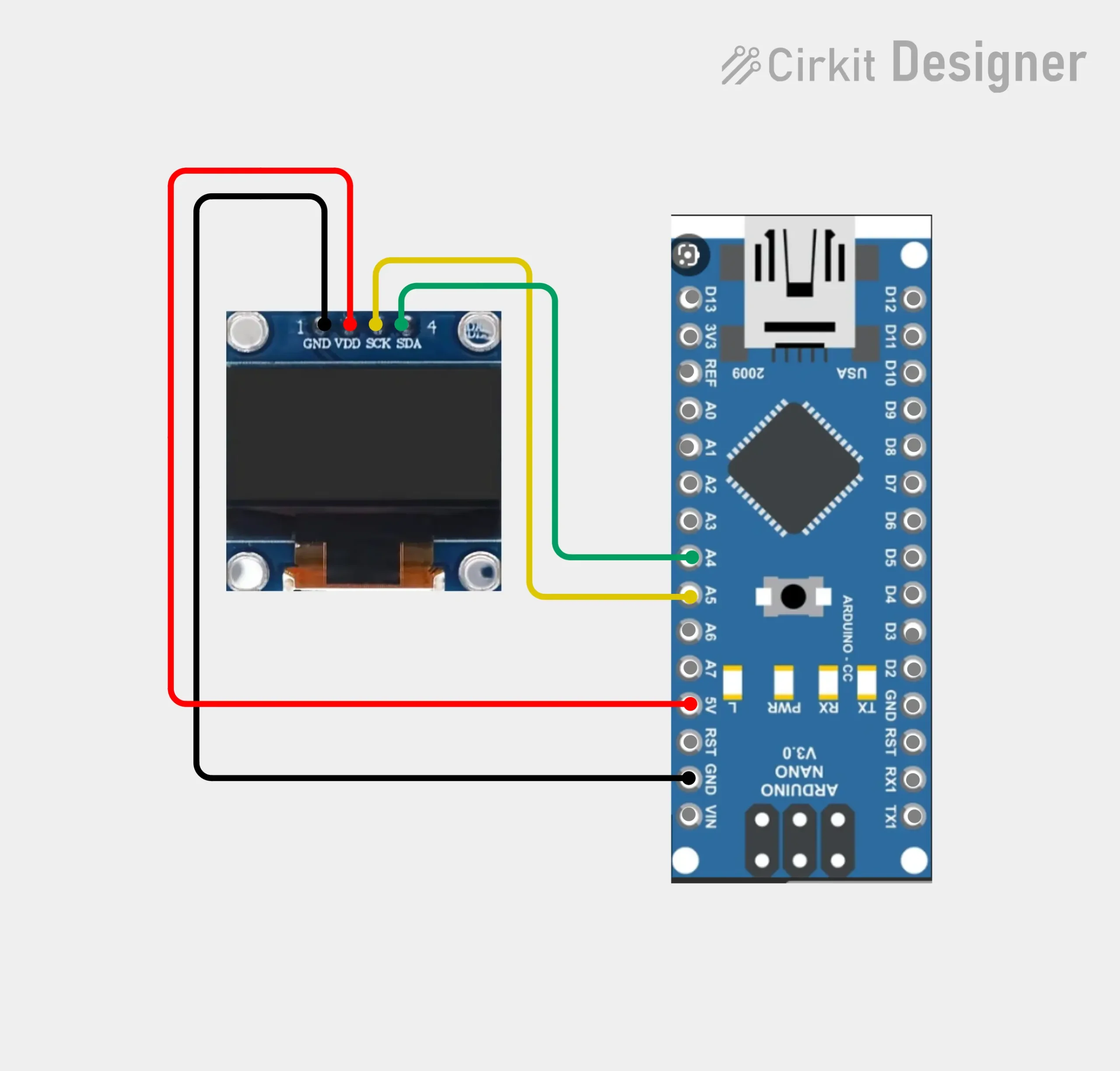
The code uses:
#define OLED_I2C_ADDRESS 0x3C
#define OLED_I2C_CLOCK 400000ULTherefore, the expected OLED address is 0x3C, and the firmware requests a 400kHz I2C bus.
Test Button Connections
| Button connection | Destination |
|---|---|
| Button terminal 1 | Arduino D7 |
| Button terminal 2 | GND |
| 10kΩ resistor | Between D7 and 5V |
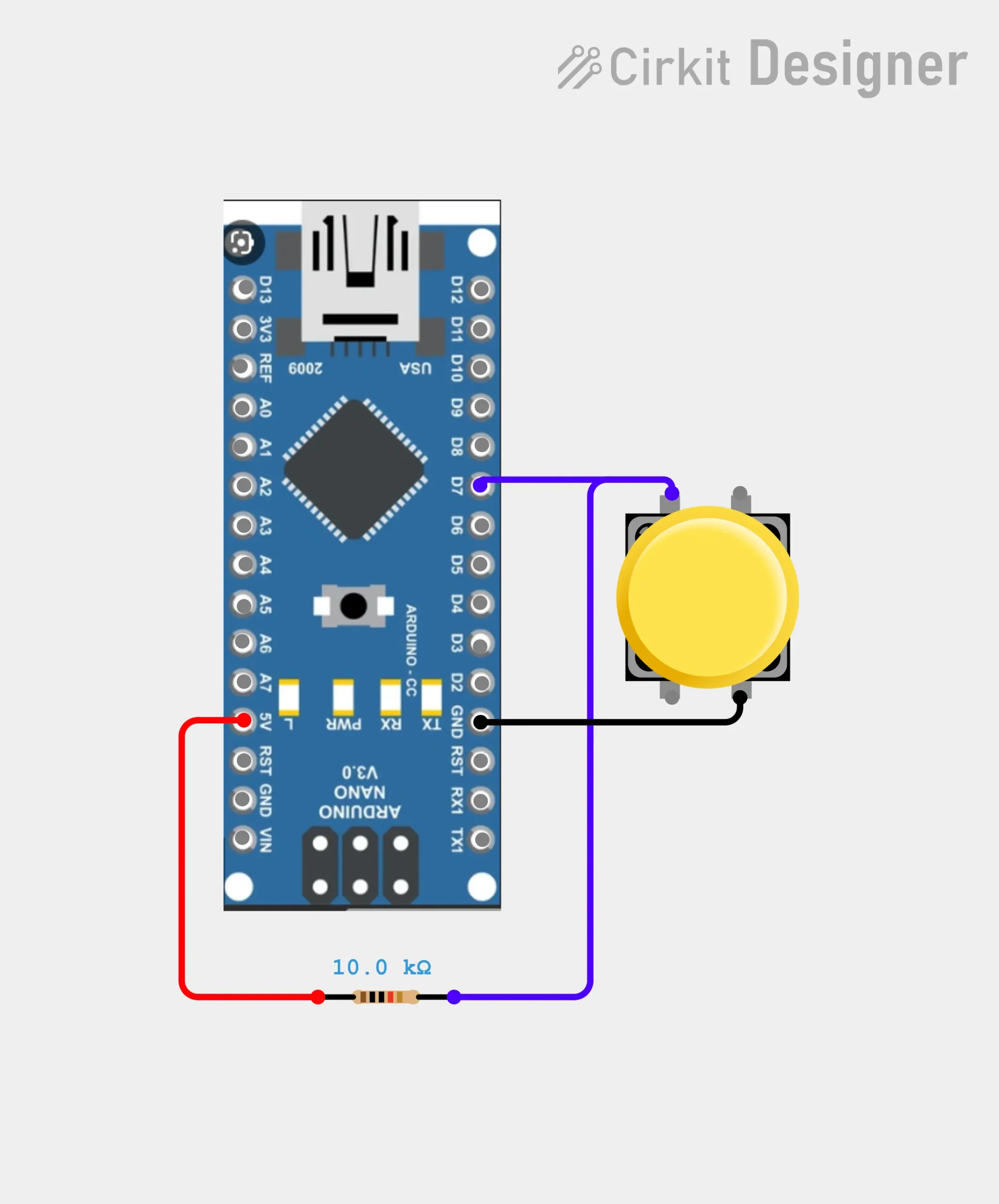
The code configures D7 as a normal input and expects an external pull-up resistor. Pressing the button pulls D7 low.
Power-Supply Connections
For a battery-powered version:
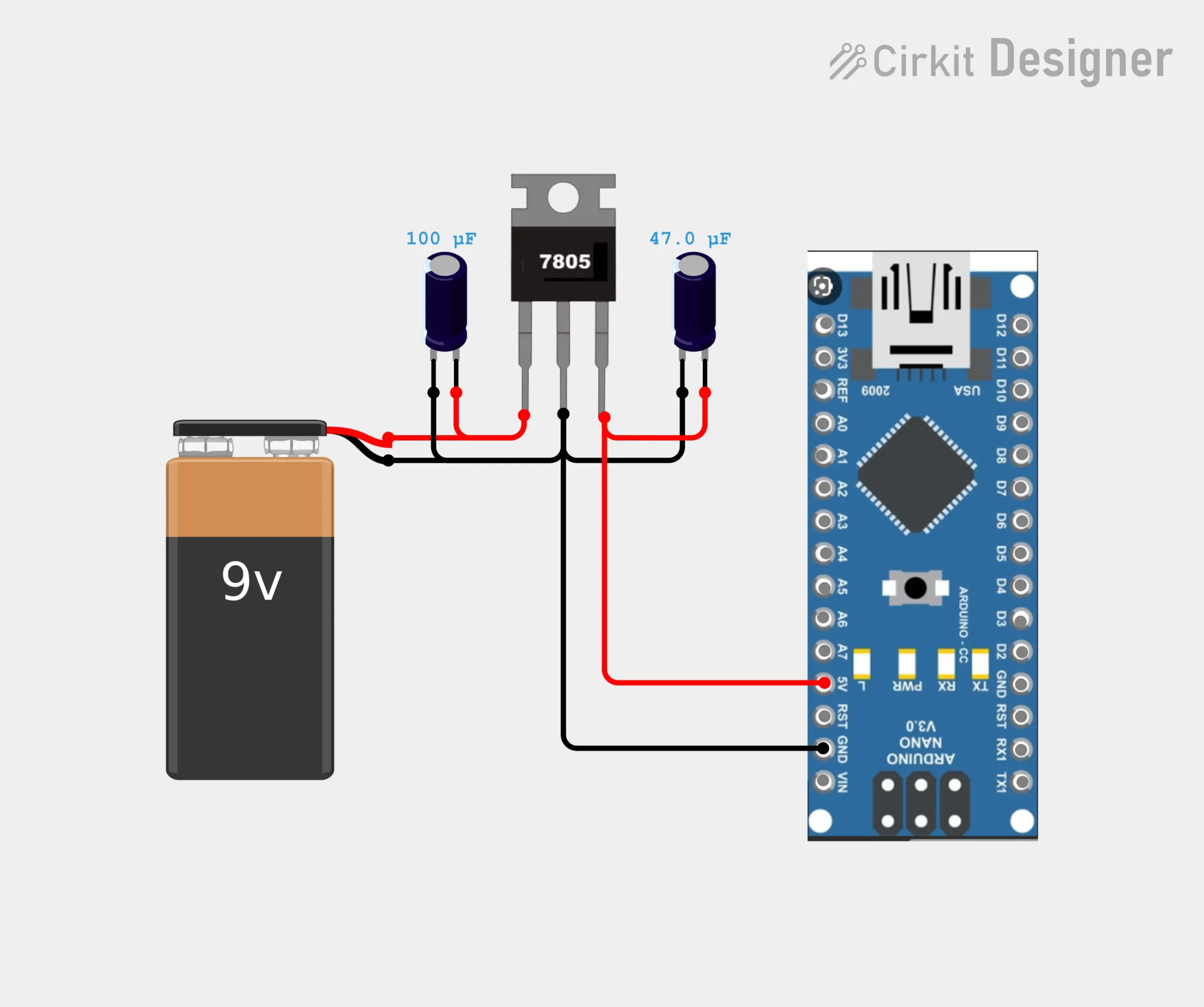
Suggested capacitor placement:
- 100µF from the 7805 input to ground
- 47µF from the 7805 output to ground
- 0.1µF ceramic close to the regulator or Arduino supply pins
Observe the polarity of both electrolytic capacitors.
The L7805 is a fixed 5V positive regulator. The Arduino Nano documentation also permits a regulated 5V supply to be connected through its 5V power pin.
Important: Keep the battery power switched off while connecting the Nano to USB for programming unless the power system includes proper isolation or source selection.
Step-by-Step Assembly Guide
Step 1: Measure the Six Precision Resistors
Before soldering, use a reliable digital multimeter to measure each resistor separately.
Record the values as:
- RL1
- RH1
- RL2
- RH2
- RL3
- RH3
Do not assume all three nominally identical resistors have exactly the same value.
Example:
RL1 = 679.6Ω
RL2 = 681.1Ω
RL3 = 678.9Ω

RH1 = 469.7kΩ
RH2 = 471.2kΩ
RH3 = 470.4kΩStep 2: Mount the Arduino Nano Headers
Solder female header strips to the veroboard so that the Arduino Nano can be removed later.
Using headers makes it easier to:
- Replace the Nano
- Reprogram the board
- Inspect solder joints
- Reuse the Nano in another project
- Modify the onboard D13 LED circuit if required
Step 3: Build the Power Section
Install the 7805 regulator, input terminal, switch and capacitors first.
Check the regulated output with a multimeter before installing the Nano. The output should be close to 5V.
Never insert the Arduino if the regulator output is significantly above 5V.
Step 4: Install the Three Test Terminals
Mount the three-pin connector in an accessible position and clearly label it:
TP1 TP2 TP3Keep all wiring between the test connector, resistors and Arduino pins as short as practical. Long wires add parasitic resistance, inductance and capacitance.
Step 5: Install the Six Test Resistors
Connect each resistor to the correct digital pin and test terminal:
D8  -- 680Ω  -- TP1
D9  -- 470kΩ -- TP1

D10 -- 680Ω  -- TP2
D11 -- 470kΩ -- TP2

D12 -- 680Ω  -- TP3
D13 -- 470kΩ -- TP3Do not interchange an RL and RH resistor. Incorrect placement can cause wrong component identification and inaccurate readings.
Step 6: Connect the Direct ADC Lines
Connect:
A0 directly to TP1
A1 directly to TP2
A2 directly to TP3These connections should not include a series resistor unless the entire firmware and measurement calculations are redesigned for it.
Step 7: Connect the OLED
Connect the OLED to 5V, ground, A4 and A5.
Keep the I2C wires away from long test leads and the battery input wire.
Step 8: Connect the Push Button
Connect one side of the button to D7 and the other side to ground.
Install the 10kΩ resistor between D7 and 5V.
Step 9: Inspect the Veroboard
Before applying power, check for:
- Copper-track bridges
- Reversed electrolytic capacitors
- Incorrect 7805 orientation
- Open ground connections
- Swapped 680Ω and 470kΩ resistors
- Shorts between D8–D13
- Shorts between A0–A2
- Incorrect OLED wiring
- Incorrect battery polarity
Preparing the Arduino Code
Install the Required Library
The firmware uses:
#include <Wire.h>
#include <U8g2lib.h>Wire is normally included with the Arduino core. Install the U8g2 library through the Arduino IDE Library Manager.
Select the Correct Board
In the Arduino IDE, select:
Board: Arduino Nano
Processor: ATmega328PSome clone Nano boards require:
Processor: ATmega328P (Old Bootloader)Select the correct COM port before uploading.
Entering the Exact Resistor Values
The firmware stores the default test-resistor values using scaled integers.
680Ω Resistor Conversion
The RL values use units of 0.1Ω:
Firmware value = measured resistance in ohms × 10Example:
679.6Ω × 10 = 6796Enter it as:
#define DEFAULT_RL1_TENTH_OHM 6796U470kΩ Resistor Conversion
The RH values use units of 10Ω:
Firmware value = measured resistance in ohms ÷ 10Example:
469700Ω ÷ 10 = 46970Enter it as:
#define DEFAULT_RH1_TEN_OHM 46970UConfigure all six values:
#define DEFAULT_RL1_TENTH_OHM 6796U
#define DEFAULT_RH1_TEN_OHM   46970U

#define DEFAULT_RL2_TENTH_OHM 6811U
#define DEFAULT_RH2_TEN_OHM   47120U

#define DEFAULT_RL3_TENTH_OHM 6789U
#define DEFAULT_RH3_TEN_OHM 47040UThese defaults are copied into EEPROM when the existing calibration record is missing, incompatible, outside its permitted range or has an invalid CRC.
Important Firmware Settings
#define MEASUREMENT_PASSES 3
#define DEFAULT_STABILITY_PERCENT 3
#define MIN_STABILITY_PERCENT 2
#define MAX_STABILITY_PERCENT 10
#define RESULT_TIMEOUT_MS 15000UL
#define BUTTON_LONG_PRESS_MS 1500UL
#define CHARGED_COMPONENT_WARNING_MV 100U
#define MANUAL_DISCHARGE_REQUIRED_MV 300U
#define SAFE_DISCHARGE_LEVEL_MV 10UMeasurement Passes
The code requires exactly three passes. Do not reduce this value without modifying the snapshot and median-processing logic.
Stability Percentage
The default tolerance is 3%.
A smaller value provides stricter validation but may reject more components. A larger value accepts more variation but may produce less repeatable measurements.
For a properly assembled tester, 3% is a suitable starting point.
Result Timeout
The displayed result remains visible for 15 seconds:
#define RESULT_TIMEOUT_MS 15000ULIncrease this value when more reading time is required.
Uploading the Firmware
- Turn off the external battery supply.
- Connect the Nano to the computer through USB.
- Open the firmware in the Arduino IDE.
- Confirm the six measured resistor values.
- Select the correct Nano board and processor.
- Select the correct port.
- Verify the sketch.
- Upload the firmware.
- Disconnect USB.
- Switch on the regulated battery supply.
At startup, the OLED should display:
Component Tester
Circuit Diagrams
Firmware v2.2.1 OLED
SSD1306 OLED readyIt then changes to the idle screen:
Component Tester
Connect to TP1-TP3
Short: TEST
Hold: CalibrationThese startup and idle messages are defined in the supplied firmware.
How to Calibrate the Electronic Component Tester
Calibration should be performed after:
- Initial assembly
- Changing any test resistor
- Replacing the Arduino Nano
- Changing test sockets or leads
- Repairing the measurement section
- Observing incorrect low-resistance or capacitance readings
Opening the Calibration Menu
From the idle screen, press and hold the test button for approximately 1.5 seconds.
The calibration menu contains ten pages:
| Page | Setting |
|---|---|
| 1 | Stability limit |
| 2 | RL1 measured value |
| 3 | RH1 measured value |
| 4 | RL2 measured value |
| 5 | RH2 measured value |
| 6 | RL3 measured value |
| 7 | RH3 measured value |
| 8 | Open/short zero calibration |
| 9 | Factory reset |
| 10 | Exit menu |
A short press moves to the next item. A long press selects the current item.
Editing a Calibration Value
Inside an editable setting:
- One short press increases the value
- A double press decreases the value
- A long press saves the value to EEPROM
The firmware permits:
- Stability: 2% to 10%
- RL values: 500.0Ω to 900.0Ω
- RH values: 350kΩ to 600kΩ
Open-Probe Calibration
Select Open/short zero, then hold the button.
The OLED instructs you to:
- Remove every component from TP1, TP2 and TP3.
- Keep all three terminals separated.
- Hold the button to continue.
The firmware measures the small parasitic capacitance in six test directions and stores compensation values for the different terminal combinations.
Do not touch the test terminals during this step.
Short-Probe Calibration
After the open calibration, the OLED asks you to short TP1, TP2 and TP3 together.
Use a short, clean and low-resistance conductor.
Hold the button again. The tester verifies that all three probes are shorted and measures the zero-resistance or ESR offset for:
- TP1–TP2
- TP1–TP3
- TP2–TP3
The results are saved automatically in EEPROM.
Factory Reset
Select Factory reset and hold the button.
The tester asks for confirmation:
- Hold to confirm
- Tap to cancel
A factory reset restores the firmware’s compiled default resistor values, correction factors, ESR offsets and stability setting.
How to Use the Electronic Component Tester?
Testing a Two-Terminal Component
For a resistor, capacitor, diode, LED or inductor:
- Disconnect the component from its circuit.
- Discharge it completely when it is a capacitor.
- Connect the two leads to any two different test terminals.
- Leave the third terminal unused.
- Press the button briefly.
- Do not touch the component or test terminals.
- Wait for all three measurement passes.
- Read the accepted result.
The terminal order is not important because the firmware tests multiple directions automatically.
Testing a Three-Terminal Component
For a BJT, MOSFET, JFET, thyristor or triac:
- Remove the component from its circuit.
- Connect one lead to each test terminal.
- Press the test button.
- Keep the component stationary.
- Wait for the final result.
The device determines the component pinout automatically.
Why Components Should Be Tested Out of Circuit?
Other components connected to the same circuit can create parallel paths and semiconductor junctions. These additional paths may cause:
- Wrong component identification
- Incorrect resistance readings
- False diode detection
- Incorrect transistor pinout
- Unstable-contact errors
- Failed capacitor measurements
This tester is designed for isolated, unpowered components. It is not a replacement for a protected digital multimeter and must never be connected to a live circuit. The ComponentTester project documentation gives the same safety warning because typical tester probes have no high-voltage input protection.
Charged-Capacitor Safety System
Before every measurement pass, the firmware reads the voltage on all three test terminals.
Below 100mV
The automatic discharge routine proceeds without showing a charged-capacitor warning.
Between 100mV and 300mV
The OLED shows a charged-capacitor warning and attempts to discharge the component through the measurement network.
At or Above 300mV
The measurement is stopped, and the user is instructed to remove power and discharge the component manually.
Final Safety Check
After automatic discharge, the voltage must fall to 10mV or less. Otherwise, the tester refuses to continue.
These thresholds improve safety but do not make the input voltage-protected. Always discharge capacitors externally before connecting them.
Understanding the OLED Results
Resistor Example
Resistor
Pins: 1-2
R=1.47kΩWhen inductance is detected, the fourth line may display:
L=...Capacitor Example
Capacitor
Pins: 1-3
C=100µF
ESR=0.42Ω Loss=...NPN Transistor Example
NPN Transistor
Pins: E1 B2 C3
hFE=215
VBE=0.68VMOSFET Example
N-E-MOSFET
Pins: S1 G2 D3
Vth=2.10V
Cgs=1.25nFDiode Example
Diode
Pins: A1 C2
Uf=0.67V
C=...Arduino Nano D13 Onboard LED Consideration
The firmware uses D13 as the RH3 control output through the third 470kΩ resistor. D13 is also the Arduino Nano’s built-in LED pin.
Because the RH3 path is a high-impedance 470kΩ measurement path, the onboard LED circuit on some Nano designs or clones can potentially influence measurements involving TP3. This is especially relevant when measuring high resistances or very small capacitances.
Removing the onboard “L” LED is not automatically required. Use this practical test first:
- Calibrate the tester.
- Measure the same known resistor between TP1–TP2.
- Repeat between TP1–TP3.
- Repeat between TP2–TP3.
- Compare the three results.
When all pairs produce similar readings within the selected tolerance, leave the LED unchanged.
Consider removing or isolating the D13 LED only when:
- TP3 measurements differ consistently
- RH3 cannot be calibrated accurately
- High-resistance readings involving TP3 are unstable
- Small-capacitance results are noticeably different on TP3
- The Nano will be dedicated permanently to the tester
This is a hardware-dependent consideration because different Nano-compatible boards may use different LED and USB-interface circuits.
Improving Measurement Accuracy
Use Precision Resistors
Use at least 1% resistors. For a higher-quality tester, select 0.1% metal-film resistors.
The firmware can compensate for the exact value of each resistor, but it cannot fully correct:
- Excessive temperature coefficient
- Electrical noise
- Poor solder joints
- Unstable resistor construction
- Leakage across a dirty circuit board
Keep Test Wiring Short
Long test leads increase parasitic capacitance and resistance.
For accurate small-capacitance and low-resistance measurements:
- Use short terminal connections
- Avoid long jumper wires
- Keep solder joints clean
- Remove flux residue
- Keep the test terminals away from the power input
Use a Stable 5V Supply
The ADC and test-current calculations depend on the supply and internally measured reference values. A noisy or unstable supply can reduce repeatability.
Use:
- A properly regulated 5V supply
- Good ground routing
- Local bypass capacitors
- Short power wiring
Do Not Touch the Component During Testing
Your body introduces resistance, capacitance and mains-frequency noise. This is particularly noticeable when testing:
- Megohm resistors
- Picofarad capacitors
- MOSFET gates
- JFETs
- High-impedance semiconductor junctions
Clean Component Leads
Oxidized leads can cause the firmware to display:
Unstable Contact
Component changed
3 readings rejected
Then press TESTClean the leads and repeat the measurement.
Troubleshooting
OLED Does Not Turn On
Check:
- OLED VCC and ground
- A4 to SDA
- A5 to SCL
- OLED address
- 5V regulator output
- Solder joints
- Whether the display uses SSD1306 or a different controller
The firmware expects address 0x3C.
Tester Always Shows Unknown Part
Possible causes include:
- RL and RH resistors interchanged
- A0, A1 or A2 not connected
- Wrong D8–D13 order
- Poor test-terminal contact
- Powered or in-circuit component
- Damaged component
- Incorrect resistor values
- Excessive board leakage
Tester Shows Voltage Detected Without a Component
Check for:
- Residual charge on a capacitor
- Moisture or flux on the board
- Incorrect power wiring
- Short between a test terminal and 5V
- Damaged Arduino analog input
- Wrong resistor connection
- External electrical noise
Measurements Are Rejected as Unstable
Try:
- Cleaning the component leads.
- Tightening the test terminal.
- Shortening the leads.
- Repeating open/short calibration.
- Checking the 5V supply.
- Inspecting solder joints.
- Increasing stability from 3% to 4% only when the hardware is otherwise correct.
Do not immediately increase the tolerance to 10%, because that can hide a real hardware problem.
Capacitance Reading Is Too High With Empty Probes
Run the open-probe calibration again.
Ensure:
- Nothing is connected
- Probes are separated
- Your hands are away from the terminals
- The board is clean and dry
- Test wiring is short
ESR Does Not Read Zero When Probes Are Shorted
Run the short-probe section of zero calibration using a clean, low-resistance conductor.
Wrong Transistor Pinout
Verify that:
- The transistor is removed from its circuit
- All three terminals make good contact
- The component is not internally damaged
- The device is not an unsupported compound module
- The test voltage is sufficient for that specific device
Project Limitations
This DIY electronic component tester is extremely useful, but it is not a laboratory LCR meter or semiconductor curve tracer.
Limitations include:
- It is intended for unpowered components
- It has no high-voltage input protection
- Accuracy depends on resistor quality and calibration
- Very low resistance is affected by terminal and wiring resistance
- Very small capacitance is affected by board capacitance
- Large capacitors take longer to discharge and measure
- High-forward-voltage LEDs may not test reliably
- Some power MOSFETs may not switch fully at the available test voltage
- Complex modules cannot be identified as a single standard component
- In-circuit testing is generally unreliable
- Thyristor and triac results provide identification and pinout rather than detailed power parameters
The alternative ComponentTester firmware documentation similarly notes that this kind of tester is not equivalent to a dedicated LCR meter and that capacitance and inductance measurements have practical limits.
Final Result
This Arduino Nano electronic component tester combines a simple measurement circuit with advanced firmware features normally missing from basic DIY testers.
Its strongest features are:
- Automatic pinout identification
- Three-pass measurement validation
- Adjustable stability filtering
- Median-result processing
- Charged-capacitor detection
- Automatic low-voltage discharge
- Individual calibration of all six test resistors
- Open-probe capacitance compensation
- Short-probe ESR compensation
- EEPROM storage with CRC validation
- Compact SSD1306 OLED interface
When assembled with precision resistors, short wiring and careful calibration, it becomes a practical workbench tool for identifying loose electronic components, checking salvaged parts and confirming component pinouts before using them in a circuit.
Frequently Asked Questions
What is an electronic component tester?
An electronic component tester is a device that automatically identifies an unpowered electronic part and measures one or more of its parameters. This Arduino-based tester can identify resistors, capacitors, diodes, BJTs, MOSFETs, JFETs, thyristors, triacs and some inductive components.
Which Arduino board is used in this project?
This project uses the classic 5V Arduino Nano based on the ATmega328P microcontroller. The firmware depends on the ATmega328P port arrangement, particularly Port B for D8–D13 and Port C for analog terminals A0–A2. It should not be uploaded unchanged to a Nano Every, Nano ESP32 or Nano 33 board.
What display is required for the component tester?
The code is configured for a 0.96-inch 128×64 I2C OLED using the SSD1306 controller. Its default I2C address is 0x3C. Connect SDA to A4 and SCL to A5 on the classic Arduino Nano.
Why does the tester use three test pins?
Three test pins allow both two-terminal and three-terminal components to be tested with the same socket. For a resistor, capacitor or diode, any two terminals can be used. For a transistor or MOSFET, all three terminals are connected, and the firmware determines the pinout automatically.
Why are three 680Ω and three 470kΩ resistors required?
Each test terminal needs one low-range and one high-range current path. The 680Ω resistors provide a stronger test current for low-resistance and semiconductor measurements. The 470kΩ resistors provide a low-current path for high resistance, capacitor timing and high-impedance semiconductor tests.
How accurate is an Arduino electronic component tester?
Accuracy depends on the actual values of the six test resistors, the stability of the 5V supply, ADC behavior, wiring resistance, parasitic capacitance and calibration quality. Individually measuring the resistors, entering their exact values and completing open/short zero calibration significantly improves repeatability.
Can this tester measure a capacitor’s ESR?
Yes. The firmware calculates ESR for supported capacitors and compensates for the resistance of the test terminals using short-probe calibration. ESR readings are most useful when the terminal wiring is short and the probes have been zero-calibrated.
Can I test a component while it is soldered into a circuit?
In-circuit testing is not recommended. Other resistors, capacitors and semiconductor junctions connected to the component can alter the measurements and cause incorrect identification. Remove the component or disconnect enough leads to isolate it before testing.
Can the electronic component tester be connected to a live circuit?
No. Never connect this tester to a powered circuit. Its probe inputs do not have the protection found in a digital multimeter. The firmware’s charged-component detection is only an additional safeguard and is not a substitute for high-voltage input protection.
How do I start a normal component test?
Connect the component to TP1, TP2 and TP3, then press the button briefly. The firmware performs three measurement passes. When all three identifications and values agree within the stability limit, the OLED displays the median result.
How do I enter the calibration menu?
From the idle screen, hold the test button for approximately 1.5 seconds. Use a short press to move through the ten menu items and a long press to select an item. Inside an editable setting, tap to increase, double-tap to decrease and hold to save.
What does the unstable-contact error mean?
The error means the three measurement passes did not identify the same component or their numerical values differed by more than the selected stability percentage. Clean the leads, improve the terminal contact, keep your hands away from the probes and repeat the test.
Should I remove the Arduino Nano’s onboard D13 LED?
Removal is not normally required. First compare measurements using all three test-pin pairs. Consider isolating the D13 LED only when tests involving TP3 remain consistently inaccurate or unstable after correct assembly and calibration, because D13 controls the high-resistance RH3 path.
Why is a page-buffer OLED library mode used?
The Arduino Nano has only 2KB of SRAM. A full 128×64 monochrome OLED frame requires 1,024 bytes. Page-buffer mode uses substantially less memory, leaving enough SRAM for three measurement snapshots, component data, calibration records and other firmware variables.
What should I do before testing an electrolytic capacitor?
Disconnect the capacitor from its circuit and discharge it safely using a suitable resistor. Confirm that no dangerous voltage remains before connecting it to the tester. Never short a high-voltage charged capacitor directly with a screwdriver or the tester terminals.






No I haven’t
Do you have BOM?
Hi, i have made it and tested it with several componets.
But: measuring (schottkey) diodes wil not work, it gives a small capacitor.
I have tested it with other 1.08a software will do the same.
Is there an solution?
TC-T7-H Multifunction Tester
hello,
thank you for the project!
i want to ask if i can use for commercial purpose ,cheaper tester for user ,hobbies ..
best regards.