
Disclaimer: This article is sponsored by PCBWay, a leading PCB manufacturing company in China. However, PCBWay did not influence this article’s content, methodology, or conclusions. All opinions and findings expressed here are entirely my thoughts.
Nowadays, Lithium batteries power everything from smartphones to electric vehicles. However, their high energy density comes with some risks, like overcharging, overheating, and potential failure. Safeguarding these batteries is critical to prevent damage, fires, or even explosions. To overcome this problem, we have built a smart IoT battery management system using ESP32 that combines fast processing, Analog input precision, and built-in Wi-Fi.
Brief Overview of the Project
In this project, we will build a Smart IoT Battery Management System Using ESP32, allowing users to track real-time battery voltage, percentage, and temperature. The system uses an ESP32 microcontroller to read battery voltage via a voltage divider circuit and monitors temperature using an NTC thermistor. A relay module is integrated to automatically cut off charging when the battery reaches full capacity or exceeds a safe temperature threshold.
The code implements ADC averaging to enhance accuracy to reduce noise in battery voltage readings. The project also integrates with Arduino IoT Cloud, enabling remote monitoring from anywhere. Additionally, we have designed a custom PCB for this system, professionally fabricated by PCBWay, ensuring a more compact and reliable setup.
This project is ideal for IoT enthusiasts, DIY electronics makers, and battery-powered applications, providing an efficient way to prevent overcharging, improve battery health, and enable remote monitoring.
Importance of Battery Monitoring
Battery monitoring is important in modern electronics, ensuring efficient power usage, safety, and prolonged battery life. Whether used in IoT devices, renewable energy systems, or electric vehicles, an effective battery management system (BMS) prevents overcharging, deep discharge, and overheating.
Here’s why battery monitoring is essential:
- Prevents Overcharging – Extends battery life by stopping charging at optimal voltage.
- Avoids Deep Discharge – Protects batteries from damage due to excessive discharge.
- Enhances Safety – Prevents overheating and reduces the risk of fire or explosion.
- Improves Battery Efficiency – Ensures optimal performance by maintaining safe voltage levels.
- Real-Time Monitoring – Enables remote tracking of battery health via IoT.
- Automated Control – Activates or deactivates charging based on voltage and temperature.
- Prolongs Battery Life – Helps maintain a healthy charge cycle, reducing wear and tear.
- Prevents Voltage Drops – Ensures stable power supply for connected devices.
- Reduces Maintenance Costs – Early fault detection minimizes unexpected failures.
- Essential for IoT & Renewable Energy Systems – Used in solar panels, electric vehicles, and portable electronics.
Sponsorship by PCBWay
This project is proudly sponsored by PCBWay, a leading PCB manufacturing company known for its high-quality PCB fabrication, prototyping services, and quick turnaround times.
To make this IoT Battery Management System more reliable and professional, we designed a custom PCB, which PCBWay fabricated. Their affordable pricing, precise manufacturing, and multiple-layer options make them a great choice for both hobbyists and professionals.
Project Overview

Features of the Smart IoT Battery Management System Using ESP32
- Real-Time Battery Voltage Monitoring – Measures battery voltage using ESP32 ADC and a voltage divider circuit.
- Battery Percentage Calculation – Converts voltage readings into an accurate 0-100% battery level.
- Overcharge & Overheat Protection – Automatically stops charging when the battery reaches 4.2V or exceeds 45°C.
- IoT-Based Remote Monitoring – Integrates with Arduino IoT Cloud for real-time monitoring from anywhere.
- Relay Control for Automated Charging – Uses a relay module to enable/disable charging based on battery conditions.
- Custom PCB for Reliable Performance – Professionally fabricated PCB by PCBWay for durability and compactness.
- Low-Power Consumption & Optimized Readings – Implements ADC averaging for stable battery voltage measurement.
Components Needed
To build this lithium battery monitoring system, you will need the following components:
- ESP32 Development Board [https://amzn.to/43Mkhz7]
- Voltage Divider Resistors (10KΩ each)
- DS18B20 Waterproof Temperature Sensor [https://amzn.to/4l6pusU]
- 10KΩ Resistor for Temperature Sensor
- 5V Relay Module [https://amzn.to/4jBS7wm]
- LM1117 3.3V Regulator [https://amzn.to/4eyfvtV]
- TP4056 Li-ion Battery Charging Module (with protection) [https://amzn.to/4dMMyKh]
- Li-ion Battery Pack (3.7V or 7.4V)
- Battery Holder
- Connection Wire
- Breadboard or PCB (Designed via PCBWay for professional assembly)
Circuit Diagram & PCB Design Using KiCad

The TP4056 module manages charging safely and prevents overcharging/discharging.
The ESP32 monitors battery voltage and temperature while controlling charging using a relay.
(A) TP4056 Charging Module Connections
| TP4056 Module Pin | Connection |
|---|---|
| BAT+ (Battery Positive) | Connect to Battery + Terminal |
| BAT- (Battery Negative) | Ground |
(B) Battery Voltage Measurement Using Voltage Divider
Since ESP32’s ADC works at 3.3V max, we use a voltage divider to measure the battery voltage safely.
| Component | Connection |
|---|---|
| Battery Positive (BAT+) | Connect to Voltage Divider (10KΩ R1 & 10KΩ R2) |
| Voltage Divider Output | Connect to ESP32 Pin 34 (Analog Input) |
| Battery Ground (BAT-) | Ground |
Formula to get actual battery voltage:

Since R1 = R2 = 10kΩ, the battery voltage is doubled before reading.
(C) Temperature Monitoring Using NTC Thermistor
The thermistor ensures battery temperature remains within safe limits.
| Component | Connection |
|---|---|
| One leg of the DS18B20 sensor | Connected to ESP32 Pin 35 (Analog Input) |
| Another leg of the Thermistor | Connected to 10KΩ Resistor & GND |
| 10KΩ Resistor (Series Resistor) | Connected to 3.3V |
This forms a voltage divider, where resistance changes based on temperature.
(D) Relay Module for Charging Control
The relay disconnects the TP4056 module when the battery is fully charged (4.2V) or overheats (>45°C).
| Component | Connection |
|---|---|
| Relay Module VCC | 5V |
| Relay Module GND | GND |
| Relay Control Pin | ESP32 Pin 4 (Digital Output) |
| Relay Output | Connected to TP4056 Charging Input (+5V) |
- When the battery reaches 4.2V or overheats, ESP32 turns OFF the relay to stop charging.
- When the battery voltage drops below 3.0V, the relay re-enables charging.
How to Design & Order PCB From PCBWay
If you’re working on a battery management system or any other electronics project, having a professionally fabricated PCB ensures reliability and efficiency. Thanks to PCBWay, designing and ordering high-quality PCBs is now easier than ever—especially with their official KiCad plugin!
In this guide, I’ll show you how to seamlessly design, generate Gerber files, and order your PCB from PCBWay using KiCad.
Why Choose PCBWay for PCB Fabrication?

PCBWay is one of the most trusted names in PCB manufacturing in China, offering:
- High-quality PCB fabrication at affordable prices
- Fast turnaround time with global shipping
- Multiple PCB customization options (solder mask colour, thickness, finish, etc.)
- PCB assembly services if you want components pre-soldered
- A dedicated KiCad Plugin that makes ordering PCBs hassle-free
Thanks to PCBWay’s sponsorship, I was able to get my ESP32 Battery Monitoring PCB professionally fabricated, ensuring a compact, durable, and well-routed PCB design. You can do the same by following the steps below!
Step 1: Install KiCad and PCBWay Plugin
Before getting started, ensure you have:
- KiCad software installed (version 6.0 or later recommended) on your pc.
- Install PCBWay Plugin for KiCad (for seamless Gerber file generation and upload).
Installing PCBWay Plugin in KiCad
- Open KiCad and navigate to Tools > Plugin and Content Manager.
- Search for the PCBWay Plugin on the available list.
- Click Install and wait for the installation to complete.
- Restart KiCad to apply changes.
Step 2: Design Your PCB in KiCad


Once the plugin is installed, start designing your PCB:
- Create a New Project in KiCad.
- Draw the Schematic using Eeschema (KiCad’s schematic editor).
- Assign PCB Footprints to all components (Verify all footprints as necessary for PCB to generate).
- Route the PCB Layout in PCBNew (KiCad’s PCB editor).
- Use the “Freerouting” plug-in to route all the connections automatically.
- Run DRC (Design Rule Check) to ensure there are no errors.
For my ESP32 Battery Management PCB, I used custom footprints and a well-optimized layout to ensure a compact and efficient design—all thanks to the precision of PCBWay’s professional fabrication services.
Step 3: Generate Gerber Files Using PCBWay Plugin
Once your PCB layout is complete:
- Open PCBNew in KiCad.
- Click on PCBWay Plugin from the toolbar.
- The plugin will automatically generate Gerber files, drill files, and BOM (Bill of Materials).
- Review the generated files before proceeding.
This plugin eliminates manual file generation hassles, making it easy to ensure all required files are correctly formatted for PCB fabrication.
Step 4: Upload & Order Your PCB from PCBWay
- Click “Upload to PCBWay” in the plugin.
- This opens PCBWay’s website, where your Gerber files will be pre-uploaded.
- Choose PCB specifications (e.g., thickness, material, colour, quantity).
- Click “Submit Order”, complete the payment, and wait for PCB fabrication.
📌 Pro Tip: PCBWay offers student discounts and special offers for makers—perfect for hobbyists and professionals alike! So go check it out quickly.
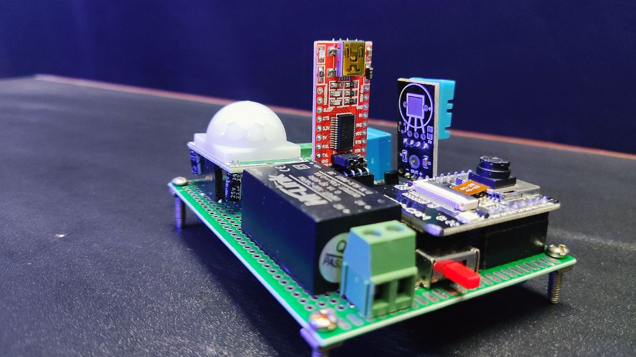
Step 5: Receive & Assemble Your PCB
Once PCBWay fabricates and ships your PCB, it’s time for assembly!
- Solder all components onto the PCB.
- Test your ESP32 Battery Monitoring System to ensure accurate voltage and temperature readings.
- Enjoy a professional-grade PCB, courtesy of PCBWay’s expert fabrication services.
Designing and ordering a custom PCB has never been easier, thanks to PCBWay’s KiCad Plugin! Whether you’re working on an IoT project, power management system, or any embedded hardware, PCBWay ensures high-quality manufacturing with a seamless ordering process.
They also provide CNC & 3D Printing, SMD Stencil, and Flexible & Rigid-Flex PCB services for your project needs. Ready to bring your PCB design to life? Order now from PCBWay and experience professional-grade fabrication! Remember to use my referral link to get an additional 5% credit bonus.
Arduino IoT Cloud Setup for Remote Monitoring
Turn your ESP32 into a smart battery guardian with real-time data tracking! Follow the steps below.
1. Create a New “Thing”

Start by logging into your Arduino IoT Cloud account. Click “Create Thing” and name it something catchy, like “Smart BMS System“.
2. Add Variables
Variables are the heart of your IoT setup. Add these four to track your battery’s health:
| Variable Name | Type | Permissions | Why It Matters |
|---|---|---|---|
| batteryPercentage | Floating Point | Read-Only | Greenlight = charging, Red = stopped. |
| batteryVoltage | Floating Point | Read-Only | Tracks real-time voltage (e.g., 3.7V). |
| temperature | Floating Point | Read-Only | Monitors battery temp (safety first!). |
| chargingStatus | Boolean | Read-Only | Green light = charging, Red = stopped. |
3. Link Your ESP32 Device
Under the “Device” tab:
- Add Device > Third Party Device > Choose ESP32 > Select Model.
- Follow the prompts to install the Arduino IoT Cloud ESP32 certificate.
- Assign your ESP32 a name (e.g., “BMS_ESP”).
- Note down your “Device ID“& “Secret Key” for future use securely.
Don’t Skip This: Double-check Wi-Fi credentials in the “Network” tab under the “Smart BMS System” Things property. A stable connection means happy data streaming!
4. Code Integration
Make your variables talk to the cloud! In your Arduino code (after including thingProperties.h):
- Sync Variables: The Arduino IoT Cloud library automatically syncs your batteryPercentage, batteryVoltage, temperature, and chargingStatus variables.
- Auto-Cut Logic: Add this snippet to control the relay based on cloud data:cppCopyvoid onChargingStatusChange() { digitalWrite(relayPin, chargingStatus ? HIGH : LOW); }
5. Build Your Dashboard (The Fun Part!)

Head to the “Dashboards” tab and create a user-friendly interface:
- Battery Percentage Gauge:
- Widget Type: Percentage
- Label: “Battery Life”
- Range: 0-100%
- Style: Color-code it (e.g., green >20%, red <20%).
- Temperature Thermometer:
- Widget Type: Gauge
- Label: “Battery Temp (°C)”
- Range: 0-100°C (add warnings >45°C).
- Charging Status LED:
- Widget Type: LED
- Label: “Charging”
- Colours: Green = true, Red = false.
- Battery Voltage:
- Widget Type: Value
- Label: “Voltage”
- Range: 0-100
Why This: A polished dashboard isn’t just pretty – it’s practical. Spot issues at a glance and impress friends with pro-level IoT skills!
Source Code
Now come to the main interesting part which is coding. This code monitors battery percentage and temperature using the ESP32 and an IoT cloud platform, controlling a relay to stop charging when the battery is full or too hot.
#include "arduino_secrets.h"
#include "thingProperties.h"

// Pin Definitions
const int batteryVoltagePin = 34;  // Analog pin for battery voltage
const int thermistorPin = 35;      // Analog pin for thermistor
const int relayPin = 4;            // Digital pin for relay control

// Battery Parameters
const float maxBatteryVoltage = 4.2;   // Max voltage for a Li-ion cell
const float minBatteryVoltage = 3.0;   // Min voltage for a Li-ion cell
const float maxTemperature = 45.0;     // Max safe temperature in Celsius
const float voltageHysteresis = 0.1;   // Hysteresis to prevent rapid relay switching

bool chargingEnabled = true; // Tracks relay status

// Voltage Divider Parameters
const float R1 = 10000.0;  // Resistor R1 in voltage divider (10kΩ)
const float R2 = 10000.0;  // Resistor R2 in voltage divider (10kΩ)

// Thermistor Parameters (NTC 5D-11)
const float thermistorNominal = 5000.0;   // Resistance at 25°C (5kΩ)
const float temperatureNominal = 25.0;    // Nominal temperature in Celsius
const float bCoefficient = 3470.0;        // Beta coefficient (B-value)
const float seriesResistor = 10000.0;     // Series resistor (10kΩ)

// **Declare missing Cloud variables**
float batteryVoltageCloud;  // Battery voltage to be sent to the cloud
bool chargingStatus;        // Charging status flag
float batteryPercentage;    // Battery percentage to be sent to the cloud
float temperature;          // Temperature reading to be sent to the cloud

void setup() {
  Serial.begin(115200);
  pinMode(relayPin, OUTPUT);
  digitalWrite(relayPin, HIGH);  // Start with relay ON (charging enabled)

  // Initialize Arduino IoT Cloud
  initProperties();
  ArduinoCloud.begin(ArduinoIoTPreferredConnection);
  setDebugMessageLevel(2);
  ArduinoCloud.printDebugInfo();
}

void loop() {
  ArduinoCloud.update();

  // Read battery voltage
  float batteryVoltage = readBatteryVoltage();
  batteryPercentage = calculateBatteryPercentage(batteryVoltage);

  // Read temperature
  float temperatureValue = readTemperature();
  temperature = temperatureValue;

  // Update Cloud variables
  batteryVoltageCloud = batteryVoltage;
  chargingStatus = chargingEnabled;  // Sync relay state with cloud

  // Charging Control Logic with Hysteresis
  if ((batteryVoltage >= maxBatteryVoltage || temperatureValue >= maxTemperature)) {
    chargingEnabled = false;  // Stop charging
  } else if (batteryVoltage <= (maxBatteryVoltage - voltageHysteresis)) {
    chargingEnabled = true;   // Resume charging when voltage drops below threshold
  }

  digitalWrite(relayPin, chargingEnabled ? HIGH : LOW);

  Serial.print("Battery Voltage: ");
  Serial.print(batteryVoltage);
  Serial.print("V, Battery %: ");
  Serial.print(batteryPercentage);
  Serial.print("%, Temperature: ");
  Serial.print(temperatureValue);
  Serial.print("°C, Charging: ");
  Serial.println(chargingEnabled ? "ON" : "OFF");

  delay(1000);  // Wait for 1 second before next reading
}

float readBatteryVoltage() {
  float sum = 0;
  const int numSamples = 10;

  for (int i = 0; i < numSamples; i++) {
    sum += analogReadMilliVolts(batteryVoltagePin);  // Read in millivolts
    delay(5);
  }

  float averageMilliVolts = sum / numSamples;
  float voltage = (averageMilliVolts / 1000.0);  // Convert mV to V
  voltage = voltage * (R1 + R2) / R2;  // Adjust for voltage divider
  return voltage;
}

float calculateBatteryPercentage(float voltage) {
  float percentage = (voltage - minBatteryVoltage) / (maxBatteryVoltage - minBatteryVoltage) * 100;
  return constrain(percentage, 0, 100);
}

float readTemperature() {
  int analogValue = analogRead(thermistorPin);
  if (analogValue == 0) return -100.0; // Error case

  float voltage = (analogValue / 4095.0) * 3.3;
  float resistance = (voltage > 0) ? (seriesResistor * voltage / (3.3 - voltage)) : seriesResistor;
  float temperature = 1.0 / (log(resistance / thermistorNominal) / bCoefficient + 1.0 / (temperatureNominal + 273.15)) - 273.15;
  return temperature;
}Testing & Results


Web Dashboard Result

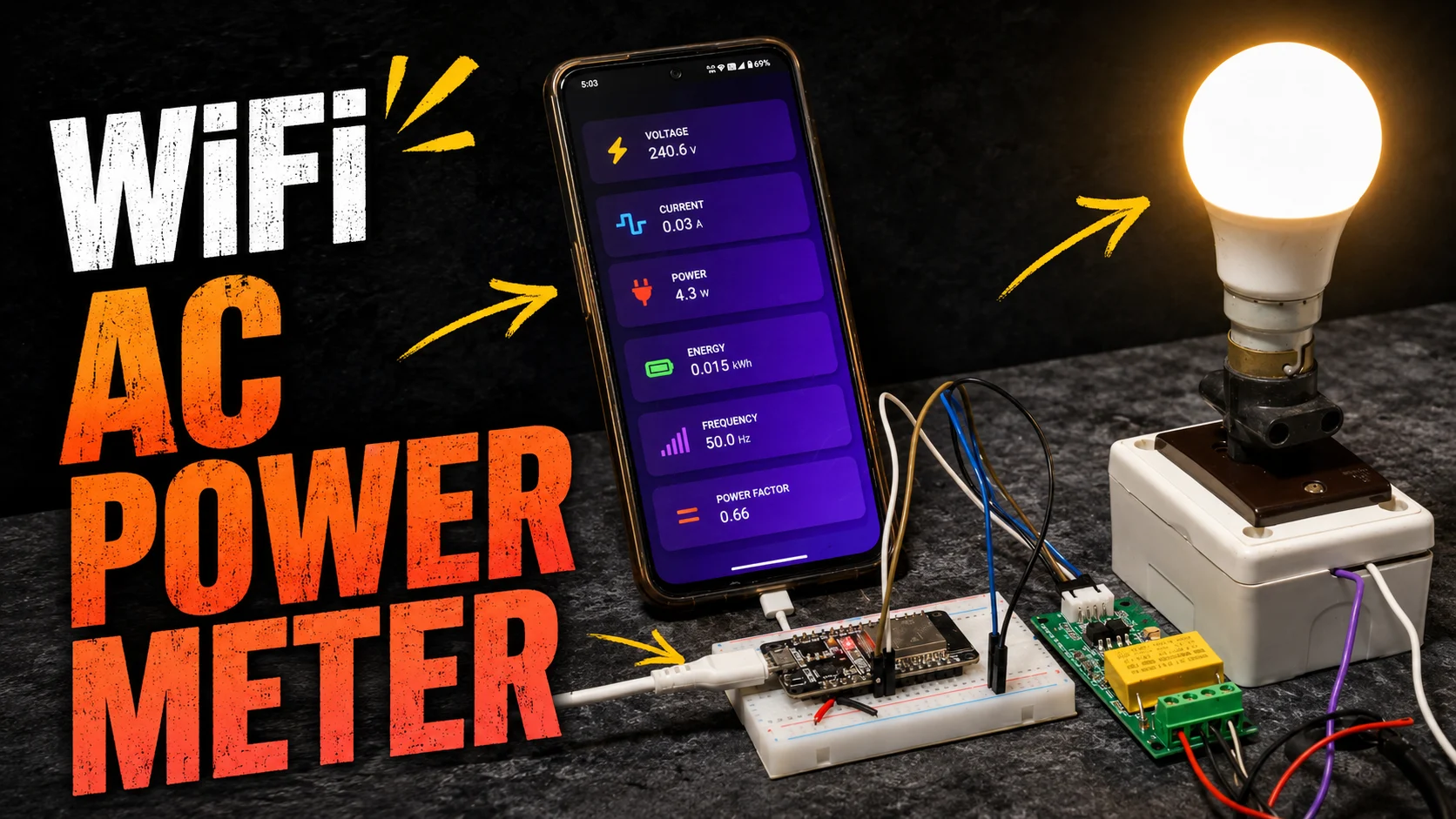
Mobile Dashboard Result

Troubleshooting Tips
If you’re facing issues with your Smart IoT Battery Management System, here are some common problems and solutions to help you debug your project efficiently.
1. Battery Voltage Reading is Incorrect or Always Zero
Possible Causes & Fixes:
- Incorrect voltage divider resistor values – Ensure R1 and R2 match the values in the code (e.g., 10KΩ each).
- Loose or wrong wiring – Double-check connections between the battery, resistors, and ESP32 ADC pin.
- ESP32 ADC scaling issue – Some ESP32 boards require calibration for accurate ADC readings. Try using analogSetPinAttenuation() in the setup.
- Battery voltage exceeds ADC input limit – Ensure the maximum voltage does not exceed 3.3V at the ESP32 ADC pin.
2. Temperature Reading is Inaccurate or Not Changing
Possible Causes & Fixes:
- Wrong thermistor resistance values in code – Ensure the thermistorNominal and bCoefficient match the thermistor you’re using.
- Loose thermistor connections – Check the wiring between the NTC thermistor and ESP32 analog pin.
- Floating analog input – If the sensor is not connected properly, it may give random temperature values.
- Wrong series resistor value – Ensure the series resistor is 10KΩ (or as per thermistor specifications).
3. Relay Not Turning On or Off Properly
Possible Causes & Fixes:
- Incorrect relay wiring – Ensure the relay module’s IN pin is connected to GPIO 4.
- Relay needs a separate power source – Some relays require 5V or more current than the ESP32 can provide. Try using an external 5V power source.
- Wrong logic control – Some relay modules are active LOW, meaning LOW = ON and HIGH = OFF. Try changing digitalWrite(relayPin, HIGH/LOW).
- Defective relay module – Test the relay manually by connecting IN to GND/VCC to check if it clicks.
4. ESP32 Keeps Restarting or Freezing
Possible Causes & Fixes:
- Insufficient power supply – Ensure you are using a stable 5V power source. Brownouts may cause random resets.
- Wi-Fi issues causing crashes – If using IoT Cloud, test without Wi-Fi to see if the issue persists.
- Faulty USB cable or port – Try a different USB cable and power adapter.
- Watchdog timer (WDT) reset – Add delays in your loop() if it runs continuously without a delay.
5. ESP32 Not Connecting to IoT Cloud
Possible Causes & Fixes:
- Incorrect Wi-Fi credentials – Double-check your SSID and password in the setup.
- Firewall blocking cloud connection – Try switching to a different Wi-Fi network.
- Weak Wi-Fi signal – Place the ESP32 closer to the router.
- IoT Cloud service down – Test by connecting to a different IoT platform (e.g., Blynk, Firebase).
6. Charging Not Stopping at Full Battery (4.2V)
Possible Causes & Fixes:
- Incorrect voltage threshold in code – Ensure that (batteryVoltage >= 4.2) properly turns off the relay.
- Delay too short for checking – Increase the delay(1000) to delay(5000) in the loop() for better control.
- Relay module not responding – Manually check if digitalWrite(relayPin, LOW); is stopping charging.
- Faulty or stuck relay – If the relay remains ON, replace it or test with a different module.
7. Overheating or Unexpected High-Temperature Readings
Possible Causes & Fixes:
- Thermistor placed too close to heat sources – Move it away from MOSFETs, regulators, or ESP32 chips.
- Incorrect beta coefficient (B-value) – Check the correct B-value for your thermistor in the datasheet.
- Bad power regulation causing heat buildup – If using a linear regulator, switch to a buck converter for better efficiency.
8. How to Debug Issues with Serial Monitor?
If something isn’t working, enable debugging using Serial Monitor:
Serial.println("Debug: Checking battery voltage...");
Serial.println("Battery Voltage: " + String(batteryVoltage) + "V");
Serial.println("Temperature: " + String(temperature) + "°C");Then open the Arduino Serial Monitor (115200 baud) to check the logs.
FAQs
Yes, this system can work with LiPo batteries, but ensure that the voltage thresholds are according to LiPo specifications for safe operations.
Modify the MIN_VOLTAGE and MAX_TEMP constants in the auto-cut logic to set your desired safe limits.
The ESP32 uses analog input pins (ADC) to read the battery voltage through a voltage divider circuit and the temperature via an NTC thermistor. The measured data is processed using custom formulas and displayed on an IoT cloud dashboard for real-time monitoring.
The ESP32 automatically disconnects the charger using a relay module when the battery reaches 4.2V (full charge) or the temperature exceeds 45°C (overheating). This auto-cutoff feature prevents battery damage and extends lifespan.
You can use Arduino IoT Cloud, Blynk, or Firebase to display real-time battery percentage, voltage, and temperature. The ESP32 updates data continuously, allowing you to monitor the battery remotely via a web or mobile app.
You can use PCBWay’s KiCad Plugin to design and order a PCB easily. The plugin automatically generates and uploads Gerber files, allowing quick fabrication with custom design options. Additionally, I already upload the Gerber file for the BMS, you just simply upload it to PCBWay and order without any hassle.
Video Output
Conclusion
Creating a lithium smart IoT battery monitoring system using ESP32 can significantly enhance safety through real-time IoT integration and automatic cutoff features. This DIY project not only empowers you as a maker but also fosters a community of enthusiasts striving for safer electronics. Share your experiences and improvements with others, and contribute to the growing field of IoT innovation!
For further exploration, check out ESP32 tutorials and Arduino IoT documentation for comprehensive guidance and additional resources.


There is error in Code And Its is not getting debugged
ok I will try to add very soon keep eye on my youtube channel.
sir give ideas for IOT enabled battery monitoring and its optimization syatems pls sir give any idea