Disclaimer: This project is proudly sponsored by PCBWay, a leading PCB manufacturing company in China. However, PCBWay did not influence this article’s content, methodology, or conclusions. All opinions and findings expressed here are entirely my thoughts.
Building a reliable IoT AC Energy Meter requires precise measurement capabilities, robust communication protocols, and safety-first design principles. This comprehensive tutorial demonstrates how to build your own real-time energy monitoring system using the PZEM-004T v3 module and ESP32 microcontroller, delivering accurate measurements of voltage, current, active power, energy (kWh), frequency, and power factor through a responsive web interface that updates without page refresh using modern AJAX techniques.
The PZEM-004T stands out from DIY sensor combinations (ZMPT101B + ACS712/SCT-013) by offering industrial-grade accuracy (±0.5%), Modbus-RTU communication reliability, and self-powered operation from the AC mains. This project addresses common implementation pitfalls including Serial2 pin mapping (GPIO16/17), power supply considerations, address persistence issues, and proper CT placement for maximum measurement stability.
You may also check the same project using ESP8266 from here: IoT Smart Energy Meter Using ESP8266 & PZEM-004T with Protection System
What Is an AC Energy Meter?
An AC energy meter is a precision instrument that measures electrical consumption in alternating current circuits, providing real-time monitoring of multiple parameters essential for energy management. Unlike simple multimeters, energy meters, it can track cumulative consumption over time, making them indispensable for residential energy monitoring, industrial load management, and IoT-based smart grid applications.
The core parameters measured include voltage (V) in volts, current (A) in amperes, active power (W) in watts representing actual energy consumption, energy (kWh) as cumulative consumption, frequency (Hz) indicating grid stability, and power factor (PF) measuring efficiency between voltage and current waveforms. Modern energy meters like the PZEM-004T v3 achieve this through dedicated metering ICs that perform real-time sampling of voltage and current waveforms, computing derived parameters using digital signal processing.
It has variety of applications. It spans from residential energy auditing and cost estimation to industrial equipment monitoring, prepaid energy systems, and building automation integration with platforms like Home Assistant and Blynk for alerts and historical analytics.
Why Choose PZEM-004T for ESP32 IoT Energy Monitoring?
PZEM-004T Capabilities and Modbus-RTU over RS485

The PZEM-004T v3 represents a significant upgrade from DIY sensor combinations, offering industrial-grade measurement accuracy of ±0.5% across all parameters. The module communicates via Modbus-RTU protocol over TTL UART at 9600 baud, supporting function codes 0x03 (Read Holding Register), 0x04 (Read Input Register), 0x06 (Write Single Register), and specialized codes 0x41 (Calibration) and 0x42 (Reset Energy).
Unlike Arduino-LCD-only builds, the PZEM-004T enables seamless integration with ESP32 web servers, cloud platforms, and home automation systems through its reliable serial communication interface. The module operates with addressable slave configurations (0x01-0xF7), allowing multiple units on a single UART bus for comprehensive multi-circuit monitoring.
PZEM-004T vs ZMPT101B + ACS/SCT DIY Stacks: Accuracy and Stability
Comparative testing reveals significant advantages of the PZEM-004T over DIY sensor combinations. While ZMPT101B voltage sensors and ACS712/SCT-013 current sensors require complex calibration and suffer from noise susceptibility, the PZEM-004T delivers factory-calibrated measurements with superior noise rejection.

Field validation studies demonstrate PZEM-004T accuracy within 0.5-4.39% across resistive, inductive, and capacitive loads, compared to error rates exceeding 12% for DIY implementations under similar conditions. The integrated design eliminates wiring complexity, reduces electromagnetic interference, and provides consistent readings across temperature variations.
Circuit Diagram

Components Required
- ESP32 DevKit Board (WROOM-32 or similar) [https://amzn.to/43Mkhz7]
- PZEM-004T v3 Module (10A built-in shunt or 100A external CT variant) [https://amzn.to/4mEtMIf]
- Breadboard & Connecting Wires [https://amzn.to/3U17ZOT]
- 3.3V DC-DC Step-Down Converter [https://amzn.to/3IZDW7Y]
- 5V 1A Power Supply for ESP32 and PZEM-004T Module
- Project Enclosure with proper ventilation
The ESP32 Serial2 interface uses GPIO16 (RX2) and GPIO17 (TX2) by default, though these pins may conflict with PSRAM on ESP32-WROVER modules, requiring alternative pin assignments.
Source Code
PCBWay Flex & Rigid-Flex PCB Capabilities for Your IoT AC Energy Meter Project

This IoT AC Energy Meter project, featuring the ESP32 microcontroller and PZEM-004T sensor, proudly sponsored by PCBWay, a global leader in PCB manufacturing known for its advanced Flex & Rigid-Flex PCB production capabilities. For creators seeking to elevate their designs beyond prototypes toward professional and durable hardware solutions, PCBWay’s flex technologies open new possibilities tailored for compact, reliable, and safe energy meter installations.
Why PCBWay Flex & Rigid-Flex PCBs Are Ideal for IoT Energy Meters
Flexible PCBs and Rigid-Flex PCBs integrate the solid foundation and ease of standard rigid boards with the adaptability of flexible circuits. This combination offers multiple advantages essential for AC energy meters operating in space-constrained, high-vibration, or heat-prone environments such as consumer electrical panels, industrial boxes, or embedded smart devices.

Core Capabilities of PCBWay Flex PCBs:
- Layer Count: 1–12 layers, enabling both simple one-layer signal jumpers or multi-layer high-density flex circuits.
- Thickness (without stiffener): 4–40 mil — ultra-thin, bendable profiles to fit behind AC mains terminals or into control panel doors.
- Tolerances:
- Single layer: ±1.0 mil
- Double layer (≤12 mil): ±1.2 mil
- Multi-layer (≤12 mil): ±1.2 mil
- Multi-layer (12–32 mil): ±8%
- With PI stiffener: ±10%
- Board Sizes:
- Min.: 0.0788” × 0.1576” (without bridge)
- Min.: 0.3152” × 0.3152” (with bridge)
- Max.: 8.668” × 27.5” — easily accommodates module-to-module flex connections.
- Electrical Precision: Impedance control tolerance ±4Ω (≤50Ω) or ±7% (>50Ω) — maintaining accuracy for high-speed sensor lines and communication buses.
- Coverlay Bridge Min.: 8 mil — maintaining mechanical stability between copper runs.

Key Features of PCBWay Rigid-Flex PCBs:
- Layer Count: Up to 26 layers for complex energy meter designs integrating power, signal, and isolation layers in one compact board.
- Fine Pitch Routing: Min. track/spacing of 0.065 mm/0.065 mm ensures high-density signal wiring (ideal for Serial2 GPIO16/17, sensor lines, Wi-Fi/Bluetooth antenna routing).
- Precision Drilling: Min. hole 0.10 mm, PTH size 0.35 mm with ±0.05 mm accuracy — critical for consistent connections to connectors and vias.
- Variable Thickness: 0.25 mm to 6.0 mm board thickness options support sturdy rigid areas and slim flexible sections.
- Copper Capability: Up to 4 oz max copper for power delivery; flexible areas 0.5–2 oz, rigid areas 1–4 oz.
- Panel Size: Max 620 mm × 500 mm — allowing multi-board panelization for production runs.
- Surface Treatments: ENIG, Electric Gold, IMM Ag, Electric Ag, HASL/HASL-LF, IMM Sn, Electric Sn, OSP, Carbon, Pt, NI-Pd-Au — choose based on corrosion resistance and solderability needs.
- Aspect Ratio: Max 13:1 (board thickness to PTH diameter) for robust multi-layer interconnects.
- Production Timeline: Build time typically 7–20 days, RFQ response in 1–2 days.
Why This Matters for the ESP32 + PZEM-004T Energy Meter
This project combines the ESP32’s powerful MCU features with the precision PZEM-004T AC energy sensor, requiring careful PCB design to achieve high reliability, safety, and compactness. With PCBWay’s flex & rigid-flex PCBs, your meter’s hardware can:
- Separate power and logic layers physically for electrical noise reduction and user safety.
- Minimize wiring complexity by embedding serial communication lines (Serial2 GPIO16/17), power decoupling capacitors, and grounding paths neatly in layered flex boards.
- Fit snugly in challenging installation environments with bendable portions maneuvering around tight enclosures or panel mounts.
- Withstand mechanical stress and vibration over years of operation, crucial for devices mounted in industrial or residential settings where durability matters.
- Reduce assembly errors and improve production throughput by integrating multiple modules and connectors on a unified flex circuit instead of separate PCBs linked by fragile wires.
PCB Design Preview & Gerber File Access
Explore the PCB Design

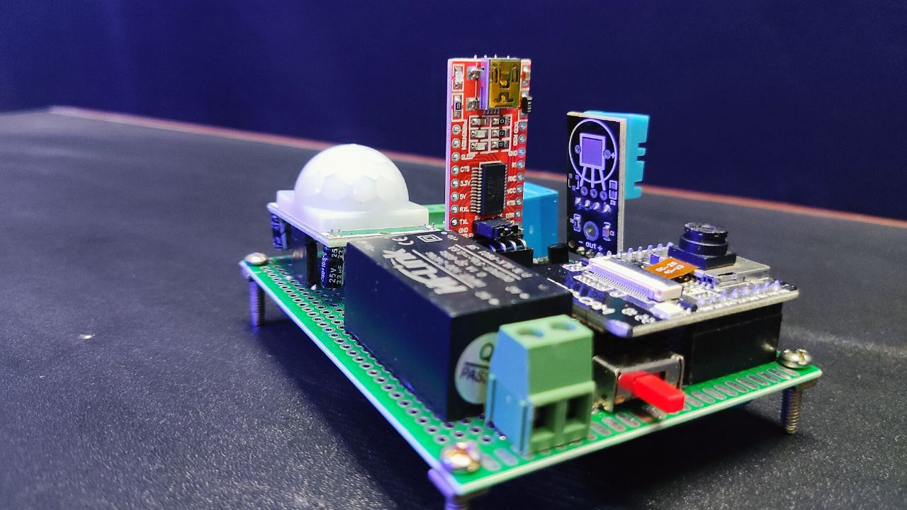
Below is a high-resolution preview of the ESP32 + PZEM-004T layout designed for compact installation and reliable measurements. This design emphasizes proper isolation, flexible mounting areas, and neat component arrangement for ease of assembly.
2D PCB Layout View
Here, a detailed 2D rendering showcases the top copper traces, component footprints, silkscreen markings, drill holes, and board outline.

3D PCB Layout View
A realistic 3D render presents the board with mounted components, solder masks, and flexible sections of the rigid-flex PCB.

Download Gerber Files for Manufacturing
Get the complete Gerber file package for this PCB, ready for upload to PCBWay or your chosen manufacturer. Files include all layers—drilling, silkscreen, solder mask—and assembly documents ensuring smooth production.
About PCBWay Sponsorship
PCBWay champions makers, engineers, and innovators worldwide by offering end-to-end PCB manufacturing and assembly services, with flexible options from simple single-layer boards to high-density rigid-flex solutions. Their rapid prototyping, DFM validation, and global shipping empower projects like this IoT energy meter to reach professional-grade quality with affordable lead times.
Understanding Components
PZEM-004T V3 100A AC Energy Meter Module
The PZEM-004T is a compact, single-phase AC power monitoring module designed for measuring key electrical parameters, including:
- Voltage: 80–260V
- Current: Up to 100A (via external current transformer)
- Active Power (Watts)
- Energy Consumption (kWh)
- Frequency (Hz)
- Power Factor (PF)
PZEM-004T V3.0 Overview

The PZEM-004T V3.0 is a popular smart metering solution for home automation and IoT projects. It communicates using the Modbus-RTU protocol over TTL serial, making it easy to integrate with microcontrollers such as Arduino and ESP32.
With built-in galvanic isolation and a non-invasive current transformer (CT), it ensures safety and reliability. Its compact size, high accuracy, and versatile measurement capabilities make it widely used in:
- IoT energy monitoring
- Smart metering systems
- Home automation projects
Key Features
| Parameter | Range & Resolution | Accuracy |
|---|---|---|
| Voltage | 80–260V, 0.1V step | ±0.5% |
| Current | 0–10A (10A model) / 0–100A (100A model), 0.001A step | ±0.5% |
| Active Power | 0–2.3kW (10A model) / 0–23kW (100A model), 0.1W step | ±0.5% |
| Power Factor | 0.00–1.00, 0.01 step | ±1% |
| Frequency | 45–65Hz, 0.1Hz step | ±0.5% |
| Energy (kWh) | 0–9999.99kWh, 1Wh step | ±0.5% |
| Over Power Alarm | User-set threshold | — |
Open CT (Current Transformer)
An Open-Type Current Transformer (CT) is a device used to measure AC current without requiring a direct electrical connection to the conductor. Instead, it senses the magnetic field produced by the current flow.

How It Works?
- When AC flows through a wire, it generates a magnetic field around the conductor.
- The open CT has a split core (hinged or clamp-type) that can be opened and placed around the wire.
- Inside the CT is a coil of wire that captures the changing magnetic field and produces a proportional, smaller AC current.
- This small current is then measured by devices like the PZEM-004T V3.0 to calculate the actual load current.
Advantages
- Non-invasive Measurement – No need to cut or disconnect the main power cable.
- Safe Operation – The CT provides galvanic isolation, preventing high voltages from reaching the measurement circuit.
- Reusable and Portable – Can be easily moved to different circuits for temporary monitoring.
- Wide Range – Available in multiple current ratings (e.g., 5A, 10A, 100A).
CT in PZEM-004T V3.0
The PZEM-004T V3.0 uses a non-invasive open CT that:
- Clips around one live wire (not the whole cable).
- Measures currents up to 10A or 100A depending on the model.
- Maintains electrical isolation between the high-voltage AC line and the low-voltage electronics.
Important: When installing an open CT, ensure it is clamped around only the live (phase) wire, not the whole cable. Clamping around both live and neutral cancels the magnetic field and results in zero readings.
Safe Wiring and Hardware Setup (Single-Phase)
Low-Voltage Connections (ESP32 ↔ PZEM-004T) with Serial2 Mapping
Establish reliable communication between ESP32 and PZEM-004T using the hardware Serial2 interface for optimal performance. Connect PZEM-004T TX to ESP32 GPIO16 (RX2) and PZEM-004T RX to ESP32 GPIO17 (TX2), ensuring proper ground reference between both modules.
Power considerations are critical: while PZEM-004T officially requires 5V, field testing confirms stable operation at 3.3V with proper decoupling. Install 100µF electrolytic capacitor across VCC/GND near the PZEM module, supplemented by 0.1µF ceramic capacitor for high-frequency noise suppression. This decoupling network prevents communication errors and measurement instability, particularly during WiFi transmission bursts.
Address configuration requires attention to prevent random device ID changes. Set a fixed address using the PZEM library’s setAddress() function during initialization, as some modules ship with unstable default addressing.
High-Voltage Connections and CT Orientation: Safety First
CRITICAL SAFETY WARNING: Working with mains voltage (120V/220V AC) presents serious electrical hazards. Always disconnect power at the circuit breaker, verify absence of voltage with a non-contact tester, and use proper PPE including safety glasses and insulated gloves.
Connect the live (L) and neutral (N) from your AC supply to the corresponding PZEM-004T terminals, ensuring tight connections to prevent heating and arcing. The current transformer (CT) must clamp around the live conductor only – never the neutral wire, as this would result in zero net current measurement.
For split-core CTs, open the transformer, pass the live wire through the center, and close securely. Verify CT orientation matches the directional arrow on the transformer body for correct power factor readings. Install the complete assembly within a properly rated electrical enclosure with adequate ventilation and strain relief for all cables.
Common Wiring Mistakes and How to Diagnose Them
- Address Flipping Issues: Symptoms include intermittent readings or device not found errors. Solution involves setting a fixed address in code and adding address persistence checks in the main loop.
- Serial Pin Confusion: Using Serial0 (GPIO1/3) instead of Serial2 causes conflicts with USB programming and Serial Monitor output. Verify GPIO16/17 connections and avoid Serial0 for PZEM communication.
- Unstable Readings: Often caused by insufficient decoupling or loose connections. Add 100µF + 0.1µF capacitors near PZEM VCC/GND and ensure solid mechanical connections at all terminals.
- Power Supply Issues: 3.3V operation requires clean power supply. Use quality USB power adapter with proper ground connection and consider external 5V supply for challenging installations.
Firmware Setup: Libraries, Code Structure, and Web Dashboard
Required Libraries and Why (PZEM004T v3, ModbusMaster, ESPAsyncWebServer, AsyncTCP)
The firmware architecture relies on four essential libraries, each serving specific functions for robust operation. PZEM004Tv30 library handles Modbus-RTU communication with automatic CRC checking and error handling. ESPAsyncWebServer and AsyncTCP libraries provide non-blocking web server functionality, enabling simultaneous sensor polling and web interface updates without performance degradation.
Library installation via Arduino IDE Library Manager ensures compatibility:
- Search “PZEM004Tv30” and install the latest version
- Install “ESP Async WebServer” by ESP32Async
- Install “AsyncTCP” dependency for ESP32 support
Install ESP32 Board
- File → Preferences → Additional Board Manager URLs → Paste this URL to the blank area “https://raw.githubusercontent.com/espressif/arduino-esp32/gh-pages/package_esp32_index.json” → Ok.
- Now go to Tools → Board → Boards Manager → Search ESP32 by Espressif Systems → Install.
This combination delivers superior performance compared to blocking web server libraries, maintaining responsive web interface while continuous sensor polling occurs in the background.
Testing the IoT AC Energy Meter
After uploading the code to the ESP32, connect the PZEM-004T to the AC mains (for example, a power strip or a specific appliance) to enable live measurements. The system is now ready for testing.
Open the Arduino IDE Serial Monitor at 115200 baud. The ESP32 will attempt to connect to the configured WiFi network. Upon successful connection, you will see a confirmation message along with the assigned IP address.

The Serial Monitor will display real-time PZEM-004T readings — including voltage, current, power, energy, frequency, and power factor — updated every 2 seconds. Ensure that no “Error” messages appear in the output.
On any device (PC, laptop, or smartphone) connected to the same WiFi network, open a browser and enter the ESP32’s IP address from the Serial Monitor. The energy meter dashboard will load, showing all measured parameters.
PC Webpage Displaying AC Energy Meter Data

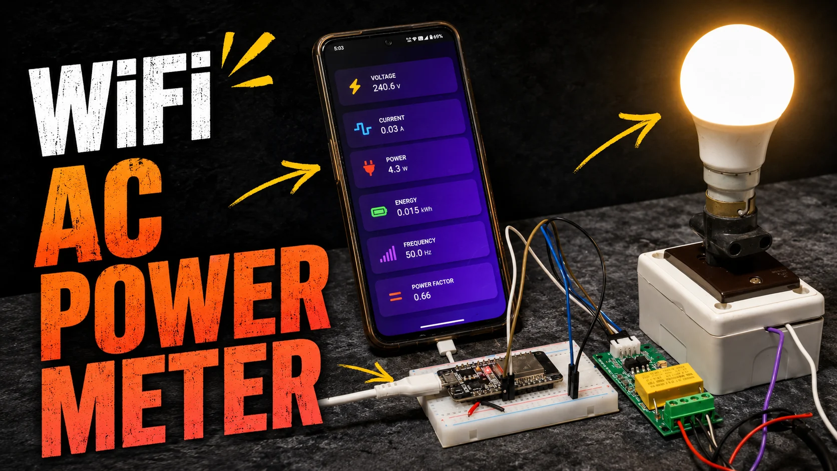
Mobile Webpage Displaying AC Energy Meter Data

You can also access the same dashboard from your mobile device by entering the same IP address. The webpage is powered by AJAX, ensuring that all parameters (e.g., Voltage: 230V, Current: 0.5A) update automatically every 2 seconds without requiring a page refresh.
For reliability testing:
- Keep the system running for 24+ hours to monitor stability and detect possible memory leaks.
- Disconnect and reconnect WiFi to confirm the automatic reconnection feature works as expected.
- Test dashboard access from an external network if remote monitoring is required.


Output Video
Comparisons: PZEM-004T vs Off-the-Shelf Smart Meters and DIY Sensors
Cost, Accuracy, Features, and Installation Complexity
Cost analysis reveals the PZEM-004T occupying a middle ground between basic DIY sensors and commercial smart meters. At approximately $15-25, the module costs 3-5x more than ZMPT101B/ACS712 combinations but delivers 10x better accuracy and reliability. Commercial smart meters range from $100-300, offering certified accuracy but limited customization options.
Feature comparison highlights DIY advantages: the PZEM-004T provides raw data access for custom algorithms, web interface personalization, and integration with any IoT platform. Commercial meters typically lock users into proprietary ecosystems with limited API access.
Installation complexity favors the PZEM approach for technically capable users. While commercial smart meters require utility coordination and certified installation, the PZEM system enables immediate deployment with basic electrical safety precautions.
When to Choose Each Option (Home DIY, Industrial, Billing)
PZEM-004T DIY builds excel for energy monitoring, research projects, home automation integration, and learning applications where customization and data access are priorities. The ±0.5% accuracy suffices for monitoring and efficiency analysis but lacks revenue-grade certification.
Commercial Smart Meters are mandatory for billing applications, utility integration, and installations requiring certified accuracy standards. These meters meet regulatory requirements but offer limited customization and higher costs.
Basic DIY sensors (ZMPT101B/ACS) suit educational projects and rough monitoring where precision isn’t critical. Higher error rates (>5-10%) limit practical applications but provide learning opportunities at minimal cost.
Revenue-grade billing requires certified meters meeting ANSI C12.20 or IEC 62053 standards – DIY solutions including PZEM-004T are unsuitable for legal billing applications.
Applications and Extensions: Cloud, Alerts, and Home Automation
Blynk Integration for Remote Monitoring and Alerts
Blynk platform integration enables smartphone monitoring and automated alerts for energy consumption thresholds. The ESP32 connects to Blynk servers using WiFi, transmitting real-time measurements to customizable dashboard widgets.
Configure virtual pins for each parameter (V1=voltage, V2=current, V3=power, V4=energy, V5=frequency, V6=power factor) and set up notification rules for overconsumption detection.
Blynk’s free tier supports basic monitoring with limitations, while paid plans unlock advanced features like historical data storage and unlimited notifications.
Home Assistant Dashboards and Automations
Home Assistant integration transforms the ESP32 energy meter into a comprehensive home automation component through MQTT or HTTP protocols. ESPHome provides seamless integration with automatic device discovery and entity creation.
Configure MQTT publishing for real-time data streams.
Home Assistant enables sophisticated automations like high-consumption alerts, device control based on power usage, and integration with presence detection for energy-saving scenarios. Dashboard cards display real-time and historical data with customizable visualization options.
Edge Analytics: Daily kWh, Cost Estimation, and PF Alerts
Implement local analytics for immediate insights without cloud dependencies. Calculate daily energy consumption by storing midnight energy readings and computing differences.
Power factor monitoring enables electrical efficiency alerts when PF drops below 0.85, indicating reactive load issues requiring capacitor correction. Low power factor increases utility bills and reduces system efficiency in industrial applications.
Real-time cost estimation helps users understand consumption patterns and peak demand periods. Implement time-of-use pricing calculations for utilities with variable rate structures.
Safety, Legal, and Compliance Notes
Electrical Safety Requirements: All mains voltage work requires proper safety procedures including power disconnection at circuit breaker, voltage verification with non-contact tester, and use of appropriate PPE (safety glasses, insulated gloves, non-conductive tools). Never attempt mains wiring without adequate electrical knowledge and proper tools.
Enclosure and Protection: Install PZEM modules and ESP32 in properly rated electrical enclosures with adequate ventilation and strain relief for all cables. Ensure proper grounding and bonding per local electrical codes. Use appropriate fuses or circuit breakers for overcurrent protection.
Legal Limitations: This project is intended for monitoring and educational purposes only. DIY energy meters including PZEM-004T systems cannot be used for revenue billing or utility-grade applications requiring certified accuracy. Consult local electrical codes and utility regulations before installation.
Standards Compliance: While the PZEM-004T achieves good accuracy for monitoring applications, it does not meet ANSI C12.20 or IEC 62053 standards required for billing purposes. Professional installation may be required depending on local regulations and insurance requirements.
Step-by-Step How-To: From Zero to Live Dashboard
Step 1 — Assemble Components and Prepare Workspace
- Gather all components from BOM checklist
- Prepare clean, well-lit workspace with proper tools
- Verify ESP32 programming capability with simple blink test
- Check PZEM-004T module operation (power LED should illuminate when connected to AC mains)
Step 2 — Wire ESP32 to PZEM-004T (LV) and Mains (High Voltage) Safely
- LOW VOLTAGE FIRST: Connect PZEM TX→ESP32 GPIO16 (RX2), PZEM RX→ESP32 GPIO17(TX2), shared GND
- HIGH VOLTAGE (POWER OFF): Connect L/N to PZEM terminals with proper torque
- Install CT around live wire only, verify directional arrow alignment
Step 3 — Flash Firmware and Configure Wi-Fi
- Install required libraries (PZEM004Tv30, ESPAsyncWebServer, AsyncTCP)
- Configure WiFi credentials and upload firmware
- Monitor Serial output for successful WiFi connection and IP address assignment
- Verify PZEM communication with address reading and basic parameter polling
Step 4 — Verify Serial Readings and Web UI Updates
- Confirm PZEM readings appear in Serial Monitor (voltage, current, power, etc.)
- Access ESP32 IP address in web browser to load dashboard
- Verify real-time updates occur every 2 seconds without manual refresh
- Test load changes reflect immediately in web interface
Step 5 — Validate Measurements and Run 24h Stability Test
- Compare readings against reference meter using known resistive loads
- Log any measurement deviations or communication errors
- Monitor system stability over 24+ hour continuous operation
- Document any WiFi disconnections or measurement anomalies
FAQs on IoT AC Energy Meter using PZEM-004T & ESP32
How does a PZEM-004T measure AC power and energy with ESP32?
The PZEM-004T uses dedicated metering ICs to sample voltage and current waveforms at high frequency, calculating active power through digital signal processing. ESP32 polls these values via Modbus-RTU over Serial2 interface every 2 seconds for web display.
Which pins do I use on ESP32 for PZEM, and why Serial2 is recommended?
Use GPIO16 (RX2) and GPIO17 (TX2) for Serial2 interface. Serial2 avoids conflicts with Serial0 used for programming and debug output. Note: WROVER modules with PSRAM may require alternative pins due to GPIO16/17 conflicts.
Can I power PZEM from 3.3V, or do I need 5V?
PZEM-004T officially requires 5V but operates reliably at 3.3V with proper decoupling capacitors (100µF + 0.1µF). However, 5V operation provides better noise margins for challenging environments.
Does this setup work for billing-grade accuracy?
No, DIY PZEM systems are for monitoring only. Revenue billing requires certified meters meeting ANSI C12.20 or IEC 62053 standards. PZEM-004T accuracy (±0.5%) suffices for energy monitoring and analysis but lacks legal billing certification.
How do I reset the energy (kWh) counter safely?
Use u003ccodeu003epzem.resetEnergy()u003c/codeu003e function call, typically during setup() or user-initiated reset. This clears cumulative energy counter but doesn’t affect other parameter measurements. Document reset events for accurate consumption tracking.
References to Leading Guides and Tutorials for Further Reading
- Random Nerd Tutorials ESP32 Web Server Guide: Comprehensive foundation for ESP32 web development and AsyncWebServer implementation
- How2Electronics PZEM-004T Tutorial: Detailed wiring diagrams and practical implementation examples
- ESPHome PZEM Integration: Professional-grade Home Assistant integration methods
- Donskytech Multi-PZEM Setup: Advanced techniques for multiple sensor configurations
- ESP32.com Forum Discussions: Community troubleshooting and advanced configuration tips
This comprehensive guide provides the foundation for building reliable IoT energy monitoring systems while maintaining safety standards and measurement accuracy suitable for residential and small commercial applications.


How to write a accurate and working code to measure phase to phase voltage, phase to neutral voltage, current, Frequency and phase angles of 3 phase supply. And very big problem is when we give the single phase supply on 3 phase input with parallel connections it shows LL voltage is 160,200,400V etc. But in real logic the voltage should be zero Plz Give us recommended suggestions 🙏
You need to copy the code using the copy button given right top corner and paste as it is in your arduino ide as it is. don’t copy via mouse, it sometimes make such errors. Then make sure you have installed the libraries named “PZEM004Tv30.h”, “ESPAsyncWebServer.h”, “AsyncTCP.h”. Then try to upload it into the ESP32.
HI , I have compile errors listed in power.txtC:\Users\daveg\OneDrive\Desktop\power\power.ino:262:1: error: ‘voltage’ does not name a type
262 | voltage = pzem.voltage();
| ^~~~~~~
C:\Users\daveg\OneDrive\Desktop\power\power.ino:263:1: error: ‘current’ does not name a type
263 | current = pzem.current();
| ^~~~~~~
C:\Users\daveg\OneDrive\Desktop\power\power.ino:264:1: error: ‘power’ does not name a type
264 | power = pzem.power();
| ^~~~~
C:\Users\daveg\OneDrive\Desktop\power\power.ino:265:1: error: ‘energy’ does not name a type
265 | energy = pzem.energy();
| ^~~~~~
C:\Users\daveg\OneDrive\Desktop\power\power.ino:266:1: error: ‘frequency’ does not name a type
266 | frequency = pzem.frequency();
| ^~~~~~~~~
C:\Users\daveg\OneDrive\Desktop\power\power.ino:267:1: error: ‘pf’ does not name a type
267 | pf = pzem.pf();
| ^~
C:\Users\daveg\OneDrive\Desktop\power\power.ino:270:1: error: expected unqualified-id before ‘if’
270 | if (isnan(voltage)) voltage = 0;
| ^~
C:\Users\daveg\OneDrive\Desktop\power\power.ino:271:1: error: expected unqualified-id before ‘if’
271 | if (isnan(current)) current = 0;
| ^~
C:\Users\daveg\OneDrive\Desktop\power\power.ino:272:1: error: expected unqualified-id before ‘if’
272 | if (isnan(power)) power = 0;
| ^~
C:\Users\daveg\OneDrive\Desktop\power\power.ino:273:1: error: expected unqualified-id before ‘if’
273 | if (isnan(energy)) energy = 0;
| ^~
C:\Users\daveg\OneDrive\Desktop\power\power.ino:274:1: error: expected unqualified-id before ‘if’
274 | if (isnan(frequency)) frequency = 0;
| ^~
C:\Users\daveg\OneDrive\Desktop\power\power.ino:275:1: error: expected unqualified-id before ‘if’
275 | if (isnan(pf)) pf = 0;
| ^~
C:\Users\daveg\OneDrive\Desktop\power\power.ino:277:1: error: ‘server’ does not name a type; did you mean ‘Server’?
277 | server.on(“/data”, HTTP_GET, [](AsyncWebServerRequest *request){
| ^~~~~~
| Server
C:\Users\daveg\OneDrive\Desktop\power\power.ino:287:2: error: expected unqualified-id before ‘)’ token
287 | });
| ^
exit status 1
Compilation error: ‘voltage’ does not name a type