A rectifier is an electronic circuit that converts an AC signal into a pulsating DC signal and also converts the alternating current into a direct current. It is used in almost every electronic projects in our regular life. According to periodic conduction, there are two types of rectifiers we will discuss in this session i.e. Half Wave Rectifier and Full Wave Rectifier.
Here we will learn about their circuit connections, working principles and applications. But the DC signal acquired at the output still has some waves which are called ripples. To decrease these ripples at the output, a filter (Capacitor Filter) is used.
What is Filter?
Filtering is the process of the DC signal done by using a capacitor. The output from the rectifier is not a pure DC voltage. This will be mixed with some noises called ripples. Therefore, it needs to be filtered by connecting a capacitor in parallel to the output.
Different Types of Rectifiers
- Half Wave Rectifier
- Full Wave Rectifier
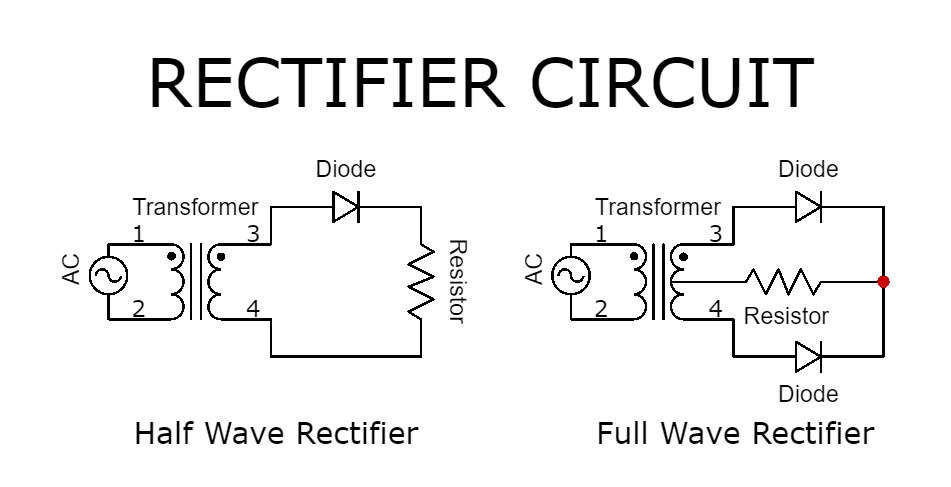
Half Wave Rectifier
It can be described as a type of rectifier that only allows the one-half cycle of an ac waveform to pass through while blocking the other half cycle.
Circuit Diagram


Working Principle of Half Wave Rectifier
Now let us discuss how half wave rectifier rectifies the ac signal into a dc signal. Firstly the primary side of the step-down transformer gains a high ac voltage. After that, the secondary low voltage is applied to the diode.
During the positive half cycle of the ac voltage, the diode gets the forward bias and during the negative half cycle, it gets the reverse bias. When the diode is in forward bias, it acts as a closed switch. And also in reverse bias condition, it acts as an open switch while no current is flowing to the load. As a result, the output voltage is equal to zero.
Characteristics Equations of Half Wave Rectifier
Ripple Factor

RMS value of the current

Form Factor
Form Factor = RMS Value / Average Value
Rectification Efficiency

Disadvantage
- An excessive amount of power loss during this rectification.
- The output voltage after rectification is low than the desired voltage.
- It consists of lots of ac ripples to its output.
Full Wave Rectifier
A full wave rectifier is defined as a rectifier that converts both the half cycle of alternating current into pulsating dc signal.
Circuit Diagram


Working Principle of Full Wave Rectifier
In the full wave rectifier circuit using a capacitor filter, capacitor C is situated across the RL load resistor. The working of this rectifier is almost the same as a half-wave rectifier. The only difference is half wave rectifier has just one-half cycle (positive or negative) whereas a full-wave rectifier has two half cycles (positive and negative).
As the input AC voltage is applied throughout the positive half cycle, then the diode D1 gets forward biased and permits current flow while the diode D2 gets reverse biased & blocks the current flow.
Throughout the above half cycle, the current in the diode D1 gets the filter and makes active the capacitor. But, the capacitor charging will occur just when the voltage which is applied is upper than the capacitor voltage. Firstly, the capacitor will not charge, as no voltage will stay among the capacitor plates. So when the voltage is switched on in the circuit, then the capacitor will get charged immediately.
Throughout this transmission time, the capacitor gets charged to the highest value of the input voltage supply. The capacitor includes the highest charge at the quarter waveform in the positive half cycle. In the end, the voltage supply is equivalent to the voltage of the capacitor. Once the AC voltage begins falling and turns into less than the voltage of the capacitor, after that the capacitor begins discharging gradually.
As the input AC voltage supply gets the negative half cycle, then the diode D1 gets reverse biased but the diode D2 is forward biased. Throughout the negative half cycle, the current flow in the diode D2 gets the filter to charge the capacitor. But, the capacitor charging occurs simply when the applied AC voltage is higher than the voltage of the capacitor.
The capacitor in the circuit is not charged fully, so the charging of this does not occur instantly. Once the voltage supply becomes higher than the voltage of the capacitor, the capacitor gets charged. In both half cycles, the flow of current will be in the same direction across the RL load resistor. Thus we acquire either a whole positive half-cycle otherwise a negative half-cycle. In this case, we can get the total positive half cycle.
Characteristics Equations of Full Wave Rectifier
Peak Inverse Voltage
Peak inverse voltage is defined as the maximum voltage that a diode can withstand in the reverse-biased condition before breakdown. The peak inverse voltage of a half-wave rectifier is Vmax. So in a full-wave rectifier, it is double that of a half-wave rectifier.
PIV = Vmax
DC Output Voltage

RMS value of the current

Form Factor
Kf = (RMS value of current/average value of current)

Peak Factor
Kp = (peak value of current / RMS value of current)

Rectification Efficiency
η = (DC Output Power / AC Output Power)
Advantage
- Efficiency is double for a full wave rectifier. The reason is that a half-wave rectifier makes use of only one-half of the input signal. A full rectifier makes use of both halves and hence double efficiency.
- The residual ac ripples are very low in the output of a full wave rectifier. The same ripple percentage is very high in the half-wave rectifier. A simple filter is enough to get a constant dc voltage from the full wave rectifier.
- We know the efficiency of the full-wave rectifier is double that of the half-wave rectifier. This means higher output voltage, Higher transformer utilization factor, and higher output power.
Disadvantage
- This is useless while a small amount of current is required to be rectified. As we know, two diodes are connected in series in a full wave rectifier and produce double voltage drop due to internal resistances.
Frequently Asked Questions
What is a Half Wave Rectifier?
It can be described as a type of rectifier that only allows one-half cycle of an ac waveform to pass through it.
What is a Full Wave Rectifier?
A full wave rectifier is defined as a rectifier that converts both the half cycle of alternating current into pulsating dc signal.
What are Ripples?
The rectifier is used to convert an ac signal to a pulsating dc signal. But in this process, there are always form unwanted ac components in the rectified dc signal. These unwanted ac components are called ripples.
What is the ripple factor?
The ripple factor is a measure of the effectiveness of a rectifier circuit. It is defined as the ratio of the RMS value of the AC component (ripples) Irms in the output waveform to the DC component VDC in the output waveform.
What is the use of half wave rectifier?
Half wave rectifier is used in the soldering iron and also a liquid mosquito repellent machine to drive the fume.
Which diode is used for the rectifier?
Schottky diodes are normally used for power rectification, and signal rectification as it requires only a forward voltage of 0.2 to 0.3 volts for forward conduction.


You should google it, there are a lot of sites explaining it in detail.
How can i choose value of capacitor for removing ripples….i meant formula to choose best value
Is your second sine wave correct? Wouldn’t all the humps be above the line?
Thank you