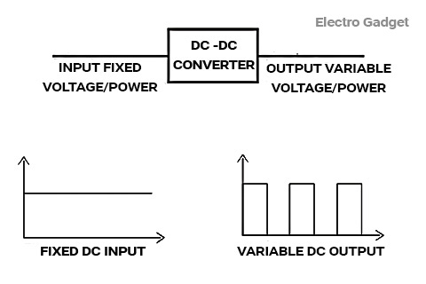
A chopper circuit is known as DC to DC converter. As compared to the transformers of the AC circuit, choppers are used to step up and step down the DC voltage. They change the fixed DC voltage to the variable DC voltage. Using these, the DC voltage supplied to the devices can be adjusted to the required amount.
Devices Used in Chopper
- Low power application: IGBT, Power BJT, Power MOSFET etc.
- High power application: Thyristor or SCR.
Principle of Operation
1. Step Down Chopper
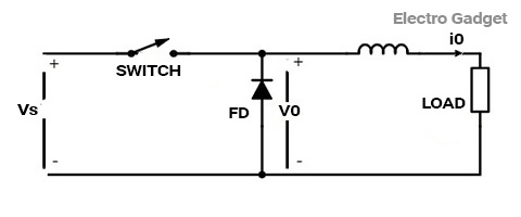
The principle of operation of the chopper can be understood from the circuit diagram below. The circuit consists of a semiconductor diode, a resistor, and a load. For all types of chopper circuits, the output voltage value is controlled by the periodic closing and opening of the switches used in the circuit. The chopper can be viewed as an ON/OFF switch that can rapidly connect or disconnect the source to load connection. Continuous DC is given as a source to the chopper as Vs and chopped DC is obtained across the load as V0.
Output Voltage and Current Waveforms
The output voltage and current waveforms of a chopper circuit are shown below. From the voltage waveform, it can be seen that during the period of TON, the load voltage V0 is equal to the source voltage Vs. However, when the interval TOFF occurs, the DC voltage step-downs to zero, thus making the load short-circuited.
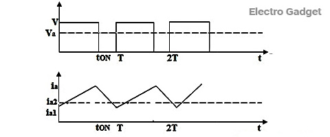
In the current waveform, it can be seen that during the interval TON, the load current rises to the maximum value. During the interval TOFF, the load current decays. In TOFF condition the chopper is off so, the load voltage becomes zero. However, load current flows through the diode FD, making the load short-circuited.
Thus, the chopped DC voltage is produced at the load. The current waveform is continuous which rises during the TON state and decays during the TOFF state.
2. Step Up Chopper
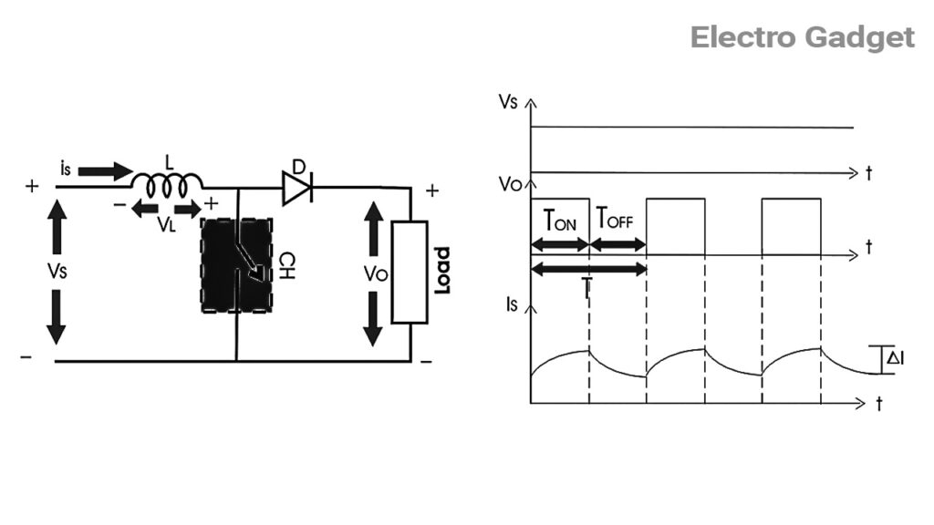
Step up chopper or boost converter is used to increase the input voltage level of its output side. Its circuit diagram and waveforms are shown below in the figure:
Operation of Step-Up Chopper
When CH is ON it short-circuits the load. Hence output voltage during TON is zero. During this period inductor gets charged. So, VS = VL

Where ΔI is the peak-to-peak inductor current.
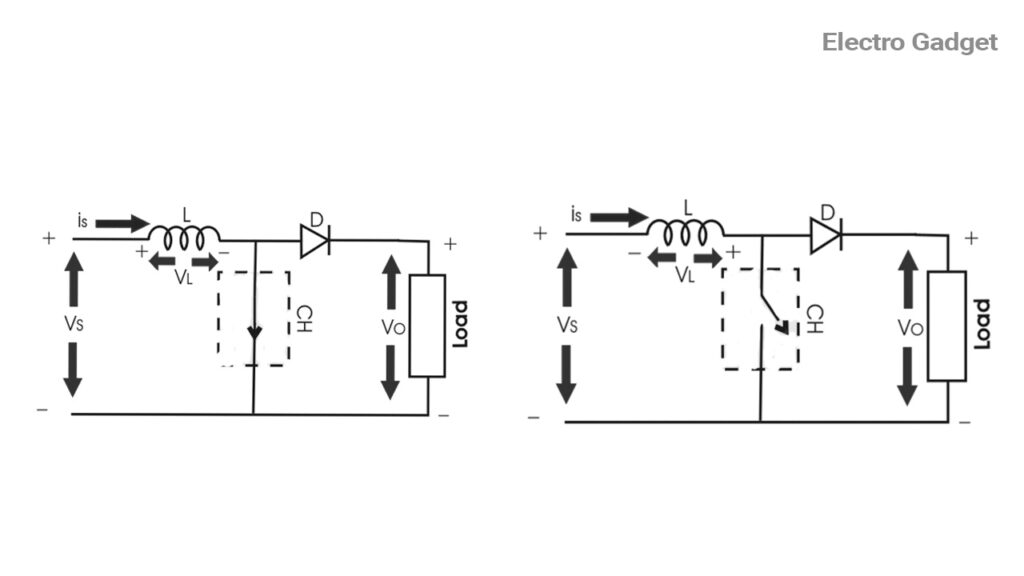
When CH is OFF inductor L discharges through the load. So, we will get the summation of both source voltage VS and inductor Voltage VL as output voltage, i.e.

Now, by equating (iii) and (iv),
(VS / L) × TON = {(VO−VS) / L} × TOFF
⇒VS (TON + TOFF) = VO × TOFF
⇒VO = (TVS / TOFF) = VS / (T−TON) / T
Therefore average output voltage, VO=VS / (1−D)
As we can vary TON from 0 to T, so 0 ≤ D ≤ 1. Hence VO can be varied
from VS to ∞. It is clear that the output voltage is always greater than the input
voltage and hence it boosts up or increases the voltage level
Difference Between Step Up And Step Down Chopper Circuit
| Criteria | Step Down Chopper | Step Up Chopper |
|---|---|---|
| Range of output voltage | 0 to V volts | V to +∞ volts |
| Position of chopper switch | In parallel with the load | For motoring operations, motor load |
| Expression for output voltage | VL dc = D × V volts | Vo = V/(1 – D) volts |
| External inductance | Not required | Required for boosting the output voltage |
| Type of chopper | Single quadrant | Single quadrant |
| Quadrant of operation | 1st quadrant | 1st quadrant |
| Applications | Motor speed control | Battery charging/voltage boosters |
| Use | For motoring operation, motor load | For regenerative braking, motor load. |
Types of Chopper Circuit
The main element based on which choppers are categorized is the semiconductor used in the chopper circuit. Based on the positioning of this semiconductor, choppers can be made to work in any of the four-quadrant conditions. Depending on the quadrant of operation choppers are categorized as Type A, B, C, D, and E.
- Type-A chopper works in the first quadrant. In this chopper, the voltage, and current both are positive and flow in the same direction. Power from source to load and the average output voltage is less than input DC voltage.
- Type–B chopper works in the second quadrant. Here the load voltage is positive and the current is negative. Power flows from load to source. This chopper is also known as a step-up chopper.
- Type–C chopper is formed by parallel connection of Type A and Type B choppers.
- Type-D chopper is the two quadrant type B chopper and Type E chopper is the fourth gradient chopper.
Type-A Chopper First–Quadrant Chopper
This type of chopper is shown in the figure. It is known as the first-quadrant chopper or type A chopper. When the chopper is on, V0 = VS and as a result, the current flows in the direction of the load. But when the chopper is off V0 is zero but I0 continues to flow in the same direction through the freewheeling diode FD, thus the average value of voltage and current say V0 and I0 will be always positive as shown in the graph.
In a type A chopper the power flow will be always from the source to the load. As the average voltage, V0 is less than the dc input voltage VS.
Type-B Chopper or Second Quadrant Chopper
In type B or second quadrant chopper, the load must always contain a dc source E. When the chopper is on, V0 is zero but the load voltage E drives the current through the inductor L and the chopper, L stores the energy during the time Ton of the chopper.
When the chopper is off, V0 = (E+ L. (di/dt)) will be more than the source voltage VS. Because of this, the diode D2 will be forward biased and starts conducting and hence the power starts flowing to the source. No matter whether the chopper is on or off the current I0 will be flowing out of the load and is treated as negative.
Since VO is positive and the current I0 is negative, the direction of power flow will be from load to source. The load voltage V0 = (E+L .di/dt ) will be more than the voltage VS so the type B chopper is also known as a step-up chopper.
Type-D Chopper or Two Quadrant Type-B Chopper
The circuit diagram of the type D chopper is shown in the figure below. When the two choppers are ON, the output voltage V0 will be equal to VS. When V0= – VS the two choppers will be OFF but both the diodes D1 and D2 will start conducting. V0, the output voltage, will be positive again when the choppers are turned on and TON will be more than the turn-off time TOFF, as shown in the waveform below. As the diodes and choppers conduct current only in one direction the direction of the load current will be always positive.
The power flows from source to load as the average values of both V0 and i0 are positive. From the waveform, it is seen that the average value of V0 is positive thus the fourth quadrant operation of type D chopper is obtained. From the waveforms, the Average value of output voltage is given by
VO=(VSTON−VSTOFF)/T=VS×(TON−TOFF)/T
Must Read Working Principle of Chopper Circuit
Jones Chopper Circuit Working Principle
- Jones Chopper is an example of a Voltage Commutated Chopper.
- Morgan Chopper is an example of the Current Commutated Chopper.
The Jones chopper circuit is shown below. Here T1 is the main thyristor and
T2 is an auxiliary thyristor.
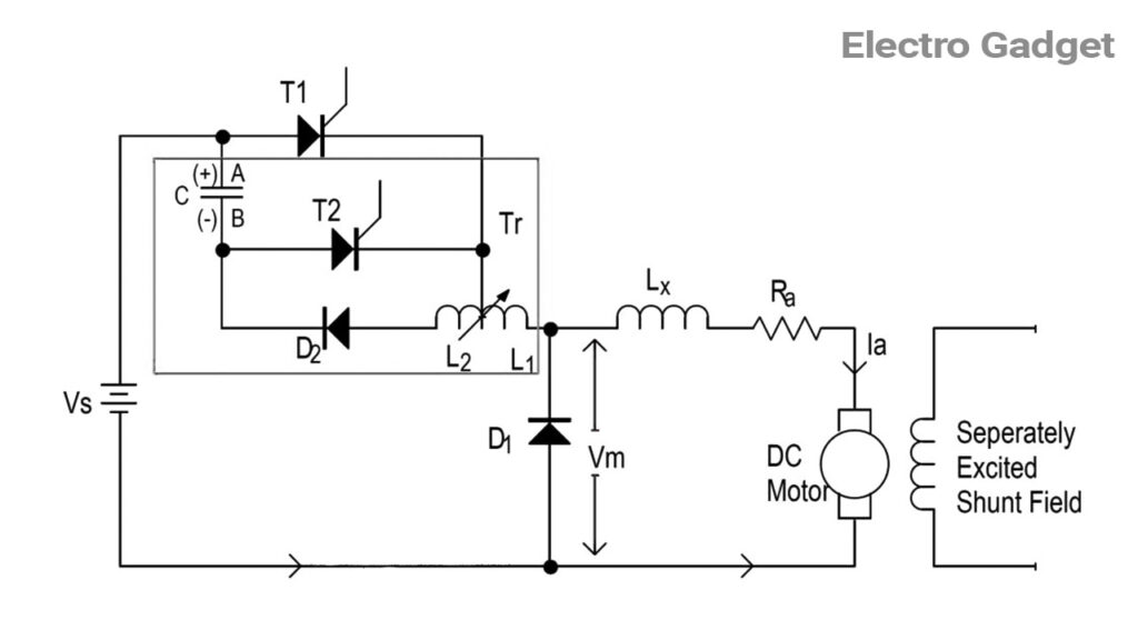
- Jones chopper is an example of a voltage commutation chopper.
- The Jones chopper circuit is frequently used for the speed control of DC motors.
- Observe that the portion of the circuit is enclosed in the blue lines.
- It is the commutating circuit for the main SCR T1.
- A charged capacitor (C) is switched by an auxiliary SCR T2 and the autotransformer (Tr) provides commutation of T1.
- In this chopper, for varying the output voltage either tON or tOFF of the main thyristor T1 can be varied.
Role of Diode
- This diode is to used carry the inductive current when T1 is turned OFF.
- Thus the diode D1 prevents the load from the high voltages appearing across it.
Morgan Chopper Circuit
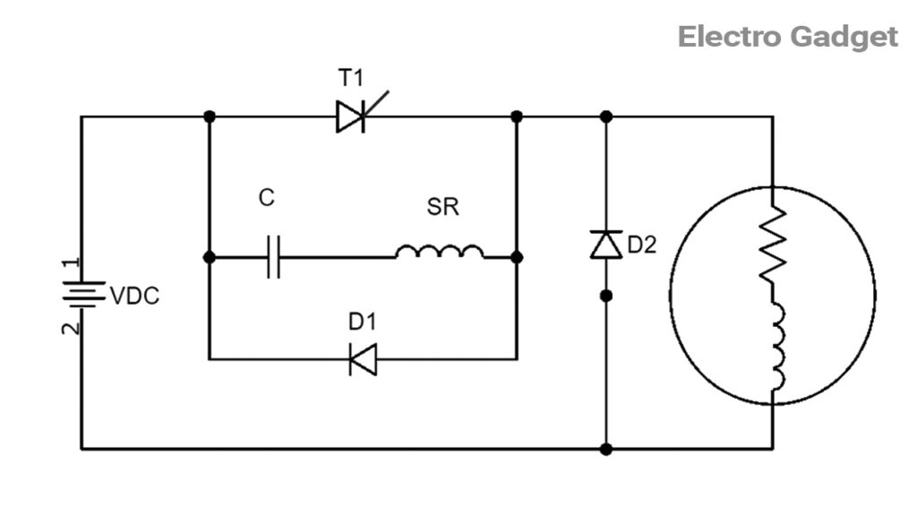
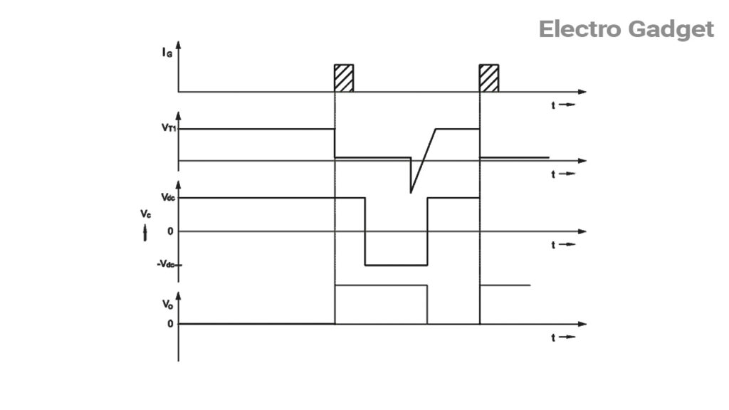
Morgan Chopper Circuit Working Principle
- When SCR T1 is switched off, the charging of the capacitor is done through the (+)Vdc – C – SR – LOAD – Vdc (-) path and the saturable reactor is in positive saturation.
- While SCR T1 is switched on, the voltage across the capacitor appears across the saturable reactor and core flux flows from positive saturation to negative saturation.
- When the core flux reaches negative saturation, the discharging of the capacitor is done through the (+)C – T1 – SCR – C(-) path.
- The capacitor and saturable reactor make a resonance circuit and its discharge time is equal to π √ LsC.
- The Ls is inductance after saturation.
- The voltage across the capacitor becomes – Vdc in a very short time and this voltage appears across the saturable reactor.
- The discharging of the capacitor is done through SCR T1 and inductance after saturation in the reverse direction when the core flux reaches positive saturation.
- As this discharging current passes through SCR T1, it will switch off SCR T1 and forward-biased diode D1.
- When SCR T1 is switched off, the load current passes through the freewheeling diode.
- The turn-on time of the SCR T1 is always constant due to the constant time of core saturation and it depends upon √ LsC.
- The average output voltage can be changed by changing only the output frequency.
- Turn on-time of the SCR is equal to the time for positive saturation to negative saturation and again positive saturation of the saturable reactor.
This type of chopper circuit assures better commutation and has better performance for lower values of chopper frequencies.
hi!,I like your writing so a lot! percentage we keep up a
correspondence more about your article on AOL? I need an expert on this house to
solve my problem. May be that is you! Taking a look ahead to peer you.
Genuinely when someone doesn’t be aware of after that its up to other viewers that they will assist,
so here it occurs.
Whoa! This blog looks just like my old one! It’s on an entirely different subject but it has pretty much the same layout and design. Outstanding choice of colours!