In this session, we will find out one of the significant circuits in a simple analogue form i.e. differential amplifier. It is basically an electronic amplifier, which has two sources of inputs and amplifies the contrast between those two input voltages.
The Operational Amplifier is inside a Differential Amplifier with highlights like High Input Impedance, Low Output Impedance, and so on.
What is a Differential Amplifier?
A differential amplifier is a circuit that is inverse of the integrator circuit. It produces an output signal where the instantaneous amplitude is proportional to the rate of change of the applied input voltage.
A difference amplifier amplifies the difference between the two input signals. An operational amplifier is a differential amplifier. However, the open-loop voltage gain of an operational amplifier is excessively high (infinite), to be utilized without a feedback connection.
Along these lines, a useful difference amplifier utilizes a negative feedback connection to control the voltage gain increase of the amplifier.
Must Read LM358 Operational Amplifier Tutorial
Types of Differential Amplifiers
- Single Input, Balanced Output
- Single Input, Unbalanced Output
- Dual Input, Balanced Output
- Dual Input, Unbalanced Output
Differential Amplifier

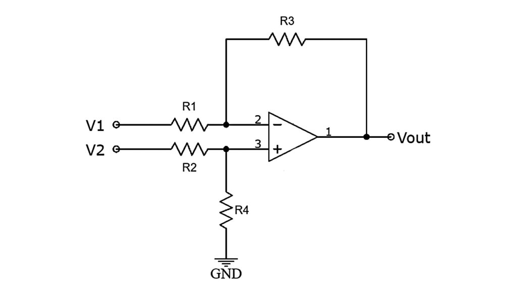
It appeared in the above circuit, is a mix of both inverting and non-inverting amplifiers. In the event that the non-inverting terminal is associated with ground, the circuit works as an inverting amplifier, and the input signal V1 is enhanced by {– (R3/R1)}.
Additionally, if the inverting input terminal is associated with ground, the circuit acts as a non-inverting amplifier. With the inverting input terminal grounded, R3 and R1 work as the feedback components of a non-inverting amplifier.
V2 is conceivably isolated across resistors R2 and R4 to give VR4, and afterwards, VR4 is amplified by (R3 + R1) / R1.
Derivation
Let V2 = 0,
VO1 = -(R3 / R1) × V1
With V1 = 0
VR4 = {R4 / (R2 + R4)} × V2
and
VO2 = {(R1 + R3) / R1} × VR4
therefore
VO2 = {(R1 + R3) / R1} × {R4 / (R2 + R4)} × V2
If the input resistances are chosen such that R2 = R1 and R4 = R3, then
VO2 = (R3 / R1) × V2
Now, according to the superposition theorem, if both the input signals V1 and V2 are present, then the output voltage is:
VO = VO1 + VO2
= {-(R3 / R1) × V1} + {(R3 / R1) × V2}
When the resistors R3 and R1 are of the same value, the output is the direct difference of the input voltages applied. By selecting R3 greater than R1, the output can be made an amplified version of the difference of the input voltages.
Input Resistance
One issue with choosing the differential amplifier resistors as R2 = R1 and R3 = R4 is that the input resistance for both inverting and non-inverting amplifiers is inconsistent.
The input resistance for voltage V1 is R1 on account of an inverting amplifier. For the non-inverting input, for example for input voltage V2, the input resistance is (R2+R4).
This difference in the input resistance makes one of the input signals be more amplified than the others.
The output condition of the differential amplifier Vout can be gotten by making the ratio R4 / R2 equivalent to R3 / R1, rather than making R2 = R1 and R4 = R3.
The input resistance won’t cause an issue if the signal source resistance is a lot littler than the input resistance. Likewise, it is typically attractive to have R2 = R1 and R4 = R3, to limit the input offset voltages.
Input Impedance
Differential input impedance is the ratio between the change in voltage between V1 and V2 to the change in current. When the op-amp working, the voltages at the inverting and non-inverting inputs are driven to be the same. The differential input impedance is thus R1 + R2.
If the op-amp was saturated then the differential input impedance would be higher = R2 + R4 + R1 + R3
Differential Gain
The differential gain of a differential amplifier is defined as the gain acquired at the output signal as for the difference in the input signals applied.
The output voltage of a difference amplifier is given as,
VO = AD(V1 – V2)
where, AD= -(R3 / R1) is the differential gain of the amplifier
Common Mode Input
A differential amplifier amplifies the contrast between the two input voltages. In a short words, a common mode input Vcm would make the input sources (V1 + Vcm) and (V2 + Vcm), which will result in Vcm being cancelled when the difference of the two input voltages is amplified.
Since the output of a practical differential amplifier relies on the ratio of the input resistance if these resistors’ ratio is not actually equivalent. At that point, one input voltage is amplified by a more amount than the other input.
Thusly, the common mode voltage Vcm won’t be totally dropped. Since it is practically difficult to coordinate resistors’ ratios perfectly, there is probably going to be some common mode output voltage.
With the presence of common mode input voltage, the output voltage of the differential amplifier is given as,
VO = AdVd + AcVc
where, Vd= Difference Voltage V1 – V2
Vc= Common Mode Voltage (V1 + V2) / 2
Common Mode Rejection Ratio (CMRR)
The capacity of a differential amplifier to dismiss common-mode input signals is expressed as the common mode rejection ratio (CMRR). The common mode dismissal ratio of a differential amplifier is numerically given as the ratio of the differential voltage gain of the differential amplifier to its common mode gain.
CMRR = ।Ad / Ac।
Preferably, the common mode voltage gain of a differential amplifier is zero. Consequently, the CMRR is preferably infinite.
Characteristics of a Differential Amplifier
- High differential voltage gain
- Low common mode gain
- High input impedance
- Low output impedance
- High common mode rejection ratio
- Large bandwidth
- Low offset voltages and currents
Differential Amplifier as Comparator
A differential amplifier circuit is a valuable operation amp circuit since it tends to be designed to either “add” or “subtract” the input voltages, by reasonably including more resistors in parallel with the input resistors.

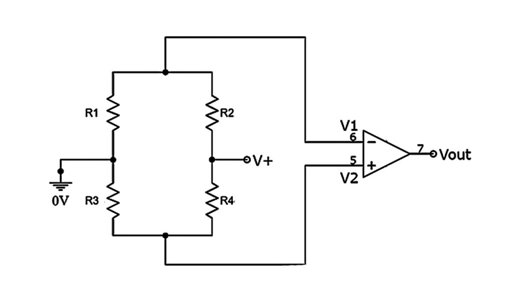
A Wheatstone bridge differential amplifier circuit configuration is as appeared in the above figure. This circuit acts like a differential voltage comparator.
By associating one input to a fixed voltage and the other to a thermistor (or LDR), the circuit identifies high or low degrees of temperature as the output voltage turns into a direct linear function of the adjustments in the active part of the resistive bridge.
A Wheatstone bridge differential amplifier can likewise be utilized to locate the obscure resistance in the resistive bridge, by contrasting the input voltages over the resistors.
Example
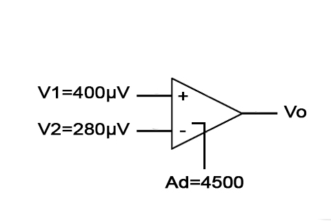
Decide the output voltage of a differential amplifier for the input voltages of 400µV and 280µV. The differential gain of the amplifier is 4500 and the estimation of CMRR is (I) 100 and (ii) 105

i) CMRR = Ad / Ac
100 =4500 / Ac
Ac = 45
Vd = (V1 – V2) = 400µV – 280µV = 120µV
Vc = (V1 + V2)/2 = 680µV / 2 = 340 µV
VO = (AdVd) + (AcVc) = [(4500 x 120) + (45 x 340)] µV = 555300 µV = 555.3 mV
ii) CMRR = 105
Ac = Ad / CMRR = 4500 / 105 = 0.045
VO = AdVd + Ac Vc = [4500×120 + 0.045×340] µV = 540015.3 µV
Note: Ideally, Ac is zero. So the output is only AdVd, which results in VO = 4500 x 120 µV = 540mV.
Frequently Asked Questions
One issue with choosing the differential amplifier resistors as R2 = R1 and R3 = R4 is that the input resistance for both inverting and non-inverting amplifiers is inconsistent.
The input resistance for voltage V1 is R1 on account of an inverting amplifier. For the non-inverting input, for example for input voltage V2, the input resistance is (R2+R4).
This difference in the input resistance makes one of the input signals be more amplified than the others.
The output condition of the differential amplifier Vout can be gotten by making the ratio R4 / R2 equivalent to R3 / R1, rather than making R2 = R1 and R4 = R3.
The input resistance contrast won’t cause an issue if the signal source resistance is a lot littler than the input resistance. Likewise, it is typically attractive to have R2 = R1 and R4 = R3, so as to limit the input offset voltages.
The differential gain of a differential amplifier is defined as the gain acquired at the output signal as for the difference in the input signals applied.
Thanks for the information