Wave Propagation: In terms of communication network, the whole process involves the transmission of information from one place to another through antennas. As we know, modulation takes place to encrypt the information onto carrier waves through analog and digital converting processes. It is the part of the carrier waves that determine how signals can propagate over any significant distance. It is used in various electronics applications.
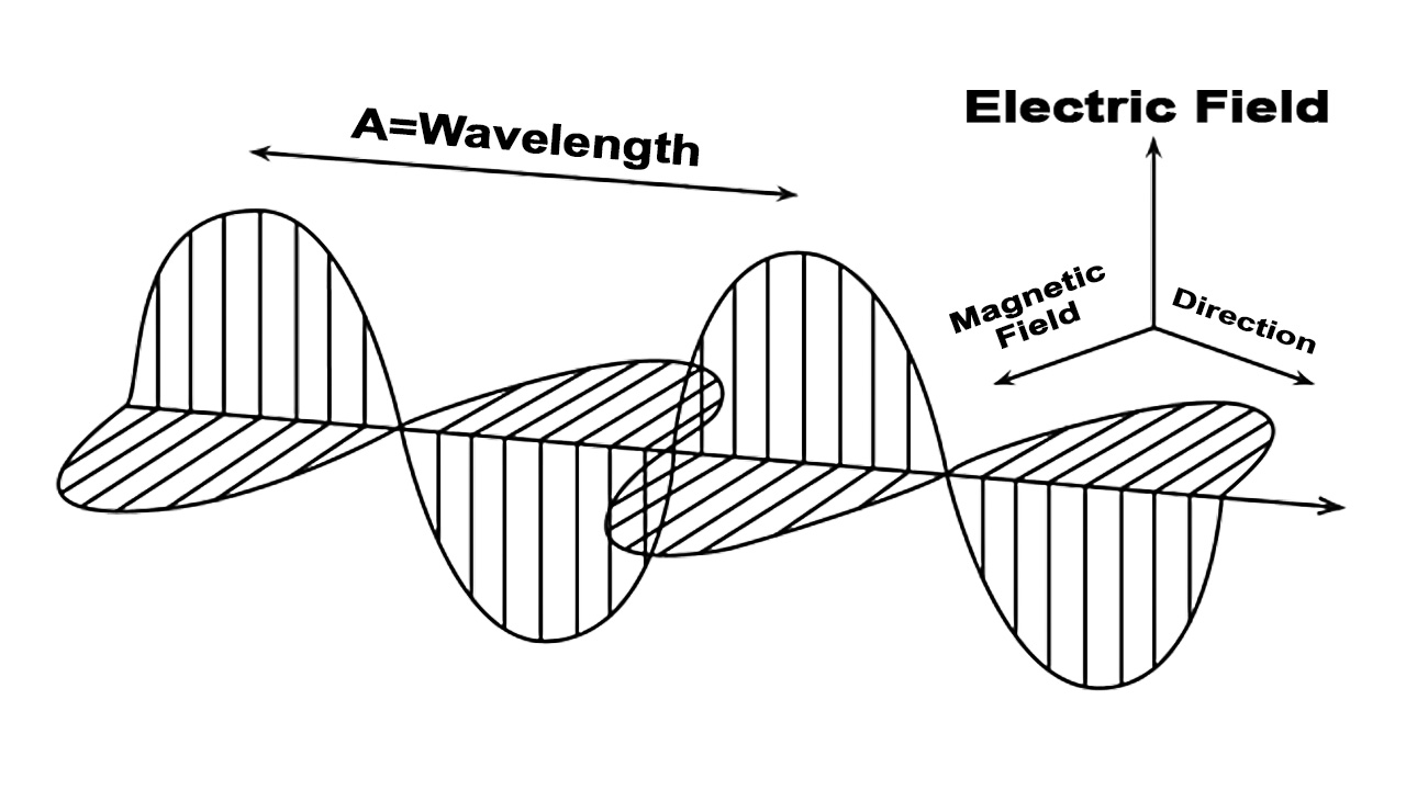
When there is a high-frequency current present in an antenna, then an EM energy (Electromagnetic energy) will be generated. Changing current produces changing magnetic current, and changing magnetic current produces changing electric field. By this process of producing changing magnetic field and changing electric field, will generate the EM waves. This journal will teach you a detailed lesson about all types of EM waves.
What is an Electromagnetic Wave?
Electromagnetic waves are formed by creating disturbance also called noise in the electric and magnetic fields. The electromagnetic waves are oscillations, that propagate through free space. They travel through free space at a light speed. These waves are known as Electromagnetic Waves as there was also electric and magnetic fields are simultaneously present. The direction of these fields is perpendicular to each other and to the direction of propagation of the wave.
We can explain this like when we throw a stone into water, then the water waves go from origin to outward which is similar to propagation. The ripples on the water surface are longitudinal. So the oscillations are in the direction of propagation, as the EM waves in contrast are ‘transverse’. So we can say there are two types of waves i.e. Longitudinal Wave and Transverse Wave.

The electromagnetic wave (EM Wave) has been used in many applications such as telecommunications, photovoltaic, light related sensors etc.
Power Density of Electromagnetic Waves
Power Density (P): First, let us assume that a point source is spread in all the direction in space as we know, the electromagnetic waves spread uniformly in all the directions in space. Now at a distance ‘Y’ from the source point, the total radiated power will spread out equally over the area of a sphere of radius ‘Y’.

The Power Density at a point at distance ‘Y’ from the isotropic source is:
P = PT/(4πr2)
Where, PT = Transmitted Power
Note:
1. Power density at that point is the power per unit area.
2. If the transmitted power, PT is constant, then the power density is inversely proportional to the square of the distance Y2.
3. This equation clearly indicates that if we increase the range to double, and keep the power density constant, then the power density must increase four times.
Example
An isotropic source is transmitting power of 5 KW. Calculate the power density at a point that is 3 KM away from the source.
P = PT/(4πr2)
P = (10 * 10) / {4π * (20*103)2}
∴ P = 1.98 * 10-6 W/m2 = 1.98 µW/m2
EM Wave Propagation
In the EM Waves, once the radiated signal leaves the antenna, it can follow any of the three routes. This is decided by the route taken by the signal to reach the receiver from the transmitter.
Different Modes of Propagation
There are three types of propagations.
- Along the surface of the earth (Ground Wave Propagation)
- Up to the layer called “ionosphere” and back (Sky Wave Propagation)
- From transmitter to receiver in a straight line. (Space Wave Propagation)
The route taken by a radiated signal depends on many factors i.e. the frequency of the signal, atmospheric conditions and the time of the day.

Ground Wave Propagation
Ground wave propagation is a type of EM wave propagation that is also known as a surface wave. It propagates over the surface of the earth with low and medium frequencies. This will actually follow the curvature of the earth and therefore can transit a distance beyond the horizon of the surface.

The important things about the ground wave propagation are as follows:
- The ground or surface wave leaves the antenna and remains closed to the earth.
- It is the strongest at the low and medium frequency ranges. The radiated signal choose the path of this wave when the frequency is between 30 KHz and 3 MHz.
- It must be vertically polarized to prevent short-circuiting of the electric field component. The EM waves should be vertically polarized if all their electric intensity vectors are vertical.
Why Ground Waves Attenuated?
- These waves induce some current into the earth surface while it passing through it. Thus they lose some energy due to absorption.
- Due to diffraction, the wavefronts will gradually tilt over. The angle of tilt is going to increase as the ground waves progress over the surface of the earth.
- This distance depends on the type of surface, frequency of operation and the transmitted power.
- The tilt angle increases with the increase in frequency. An increase in the transmitted power does not help, in increasing the range at these frequencies. This is the reason, why this propagation cannot be practically used above 3 MHz.
Extension of Service Area
The Microwave broadcast service (535 KHz to 1540 KHz) uses this wave propagation. Some of the transmitted energy travels up towards the ionosphere. In the daytime, most of the energy is absorbed by the ionosphere. But during the nighttime, an appreciable part of this energy is returned back from the ionosphere layer to the ground. Due to this condition, the service area is extended well beyond the area possible to obtain only due to ground wave.
Field Strength at a Distance Due to Ground Wave Propagation
The radiation of EM waves from the transmitting antenna by means of ground waves gives rise to electric field strength at a distance ‘a’ from the antennas. The field strength is given by.
E = (120*π*ht*I) / (λ*d)
where, E = field strength in volt/meter
120π = Z0 = characteristic impedance of free space
λ = wavelength
a = distance from the transmitter
I = antenna current
ht = effective height of transmitting antenna
Now, if the receiving antenna is placed at this point the signal received by the antenna in volts is given by,
V = (120*π*ht*hr*I) / (λ*d)
where, hr = effective height of receiving antenna
Application of Ground Wave Propagation
- AM (Amplitude Modulation) radio broadcasting operation.
- Ships communication such as radio navigation and marine mobile communication.
- Time and frequency transmissions.
Disadvantage of Ground Wave Propagation
- It has a limited range to operate higher frequencies.
- It needs a very tall antenna to operate low frequencies. This is because the antenna height should be at least (λ/4).
- High transmission power is necessary to cover the adequate range.
Sky Wave Propagation – The Ionosphere
In sky wave propagation, the transmitted signal travels into the upper atmosphere where it is bent or reflected back to earth. This bending or reflection of the signal takes place due to the presence of a layer called the ionosphere. The layers of the ionosphere and the principle of sky wave is drawn below.

Structure of Ionosphere
The ultraviolet (UV) radiation from the sun will ionize the upper layer of the atmosphere. Due to ionization, this part of the atmosphere becomes electrically charged. The atoms take an extra electron or lose one to become negative or positive ions respectively. The free electrons are also present. This layer of ions is known as the ionosphere. It is a thick but invisible layer.
Virtual Height
The incident wave returns back to earth due to refraction. In this process it bends down gradually and not sharply. But it is interesting to see that the incident and reflected rays follow the same ways as those if the signal would have been reflected from a surface located at greater height. This height is called as the virtual height.
Critical Frequency (fc)
The critical frequency of a layer is defined as the maximum frequency that is returned back to the earth surface by that layer when the wave is incident at an angle of 90 degrees to it. The critical frequency for the F2 layer is between 5 to 12 MHz.
Maximum Usable Frequency (MUF)
The maximum usable frequency (MUF) is defined for a certain value of the angle of incidence θ rather than defining it at normal as in the case of critical frequency. This definition tells us that if the angle is increased, then it is possible to operate at a higher frequency than the critical frequency fc.
MUF = Critical Frequency / cosθ = fc secθ
This equation is also known as the “Secant law”.
Skip Distance
The skip distance is defined as the shortest distance from a transmitter, measured along the surface of the earth at which a sky wave of fixed frequency returns back to the earth. The frequency should be greater than the critical frequency.
Relation between Virtual Height, Critical Frequency and MUF
The EM waves have been shown to be incident at two different angles of incidence (θ). The vertical incidence of the waves is done to obtain basic information about the ionosphere. However, to enable transmission from one point to another, the angle should be other than the vertical.
We can write the secant law as f = (fc / cosθ)
or cosθ = (fc / f) …(i)
where fc = critical frequency at vertical incidence.
f = maximum usable frequency.
now from the above picture we can write that cosθ = (h’ / [h’2 + (d/2)2]1/2 …(ii)
where h’ = virtual height.
d = distance between the transmitter and receiver.
By substituting the equation (i) and (ii) we can get
MUF fmax = fc[ 1 + (d2 / 4*h’2 ]1/2
This is the relation between the MUF, critical frequency and the virtual height of the ionosphere.
Applications of Sky Wave Propagation
- Commercial point to point communication links and military applications.
- Ship to shore and ship to ship communication system.
Space Wave Propagation
The sky wave cannot take place above the frequencies of 30 MHz. Because the ionosphere cannot reflect back such high frequencies and the ground wave dies out near the transmitting antenna itself, due to the wavefront tilting. Hence at frequencies above 30 MHz, space wave propagation is used.

This propagation takes place by the space waves or direct waves as shown in the above picture. These waves travel in a straight line directly from the transmitting antenna to the receiving antenna. The direct waves are not refracted like sky waves nor do they follow the curvature of the earth like the ground waves.
Due to the straight-line nature of the space waves, they will at some point be blocked due to the curvature of the earth. If the signal is to be received beyond the horizon then the receiving antenna must be tall enough.
Multipath Space Wave Propagation
The signal received at the receiving antenna is not just due to the direct ray coming from the transmitting antenna but also due to the ground reflected ray.
This type of reception is often observed in the TV signal reception. Due to the different path lengths of the direct and reflected waves, they undergo different phase shifts. The resultant signal strength at the receiving antenna is due to the vector sum of strengths due to all the rays at the receiver.
Application of Space Wave Propagation
- TV broadcasting, microwave links.
- Sight and satellite communication.
- Radar communication.
Duct Propagation
Duct propagation is a special type of phenomenon which is also called the “super fraction“. It is observed at very high microwave frequencies. The duct propagation explains as follows.

- As the height above the earth increases, the air density decreases and the refractive index increases. The change in the refractive index is normally linear and gradual.
- However, under certain special atmospheric conditions, a layer of warm air may get trapped above the cooler air. This happens normally over the surface of the water.
- Due to this, the refractive index will decrease more rapidly with height than usual. This happens near the earth surface normally within a distance of 30 meters above the surface.
- Due to this rapid reduction of refractive index, the microwaves will completely bend back towards the earth surface. This is similar to what happens in skywave propagation.
- Microwaves are thus continuously refracted inside the duct and reflected back by the conducting ground or water surface. These waves then propagate around the curvature of the earth over a distance of 1000 km or sometimes more.
- Thus for the duct propagation to take place the “temperature inversion” must take place as explained above.
- The region in which the super fraction takes place is called a duct. The duct can form near the earth surface or at some heights from it. It is then called the elevated duct.
It is important to note that the duct propagation can take place only for very high frequencies in the GHz range.
Difference Between Ground Wave, Sky Wave And Space Wave Propagation
| Ground Wave | Sky Wave | Space Wave |
|---|---|---|
| It exists in the frequency range of 30 KHz to 3 MHz. | It exists in the frequency range of 3 MHz to 30 MHz. | It exists in the above frequency range of 30 MHz. |
| Used for radio broadcasting (MW range). | Radio broadcasting (SW range). | TV and FM broadcasting. |
| Ground waves are vertically polarized. | vertically polarized. | horizontally polarized. |
| Ground waves tilt progressively and eventually die. This limits the range of communication. | The transmission path is limited by the skip distance and curvature of earth. | The transmission path is limited by the line of sight and radio horizon. |
| Ground wave is a surface wave that travels along the surface of the earth. | Sky wave is reflected from the ionosphere. This is how communication takes place. | It travels in a straight line from the transmitter to receiver through space. |
| It has a range of a few hundred kilometres. | Range of a few thousand kilometres. | The service range is not more than 100 Km. |
| Power loss takes place due to absorption by the ground and tilting of waves. | Takes place due to the absorption of energy by the layers of the ionosphere. | Takes place due to the power absorption and scattering by the tall and massive objects. |
Frequently Asked Questions
Why do we get better frequency reception at night?
From the above picture, we can see the F1 and F2 layers combine each other to form a new layer. While the other two lower layers D and E disappeared. As we know in day times, these two lower layers take place to absorb the signal. But in the nighttime, this does not happen due to the absence of these two layers. This improves the strength of the reflected signal and hence the quality of reception at night.
Why is Operating fc< MUF?
The attenuation of a wave travelling through the layers of the ionosphere is inversely proportional to the square of the frequency. Naturally, the operating frequency should be as high as possible which is equal to MUF. However practically, the operating frequency is just slightly less than the MUF (about 10 to 15% less than MUF). This is done to counteract the continuous changes taking place in the ionosphere.
How to increase the Maximum Radio Range?
The maximum radio range dmax can be increased by increasing the heights of the transmitting and receiving antennas. It is used for TV transmission. In order to increase the radio range, the transmitting antenna is located on top of the mountains.
What is the use of wave propagation in communication?
It is used for line of sight (LOS) communication and satellite communication.
What is required for a wave to propagate?
EM Waves transmit energy by absorption and re-emission of wave energy by the atoms in the medium. The atoms absorb the wave energy, undergo vibrations and pass the energy by re-emission of EM Wave of the same frequency. The optical density of the medium affects the propagation of EM waves.
What type of propagation is used in AM?
Ground Waves are used for low bandwidth transmissions such as Amplitude Modulation (AM) radio broadcasting.


I like studies further information of the hf.