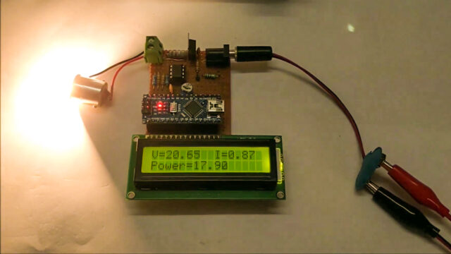
In this tutorial, I will tell you the best way to make an Arduino Wattmeter, a device that can be used to measure the power consumed by a load. With this project, this circuit can likewise go about as a Voltmeter and Ammeter to measure voltage and current.
Measuring voltage, current, and power is a fundamental assignment of any hardware engineer. For estimating voltage and current, we can use basic handheld multimeters as they give both the range and exactness for typical utilization. Yet, so as to measure the power, you have several choices from basic wattmeters to complex power analyzers and power meters.
Imagine a scenario in which I revealed to you that you can make your own Wattmeter with simple parts as a DIY project. Rather than purchasing a promptly accessible and costly Wattmeter, you can easily make your own Arduino Wattmeter. I will clarify all the essential advances required for the project.
Must Read Top Arduino Projects
About This Project
There are various ways that you can actualize the Arduino Wattmeter Project. One of the simple ways is to interface a voltage sensor and a current sensor with Arduino, measure the voltage and current qualities, and lastly, with some arithmetic, you can compute the power in watts. In spite of the fact that utilizing sensors can give exact outcomes, where is the fun in utilizing sensors on the off chance that you can design the whole system yourself?
This is advantageous in the event that you are an understudy and attempting to get the hidden ideas. The strategy which I will actualize includes the total structure of the circuit.
For simplicity of comprehension, I will isolate the circuit into equal parts: Sensor Part and Control Part. The Sensor part of the circuit is answerable for estimating the voltage over the load and current through the load. Both these qualities, which are simple in nature, are given to the Arduino to its ADC. Arduino changes over these qualities to digital values and makes a couple of counts as presentations of the outcomes on the LCD.
Project

Circuit Diagram

Components Required
- Arduino
- 16×2 LCD Display
- LM358 Op-Amp
- 7805 Voltage Regulator
- Resistors (1 Ω/3W, 1 KΩ, 2.2 KΩ, 10 KΩ, 20 KΩ)
- 10 KΩ Potentiometer
- Capacitors (100nF, 0.1µF)
- Push ON-OFF Button
- Connecting Wires
- 12V Power Supply
Working Principle of Arduino Wattmeter
In the sensor part of the circuit, there are two sections that are responsible for measuring the voltage and current. For measuring the voltage, a voltage divider circuit is introduced to utilize a 10 KΩ and a 2.2 KΩ resistor.
Utilizing these resistors, you can measure voltages up to 24V. These resistors help us bring the voltage range from 0V to 5V, which is the range Arduino can work.
Presently, going to the current measurement, Arduino or any Microcontroller so far as that is concerned can just accept Analog voltage as input i.e. it can only read voltages. In the event, that Arduino can just understand voltages, at that point how can we measure current?
So as to measure current, you need to change over the current to a suitable voltage. Here comes ohm’s law to the salvage. According to Ohm’s Law, the voltage drop over a load is corresponding to the current. Thus, a little shunt resistor is put in for the load. By measuring the voltage over this resistor, we can measure the current.
The shunt resistor utilized here is 1Ω/3W. In any event, when the load draws a current of 1A, the voltage over the shunt resistor is just 0.2V.
This value is low for Arduino’s ADC circuit. Thus, I have utilized LM358 Op-Amp in a non-inverting amplifier mode to enhance the values given to the Arduino. The voltage divider network for the feedback control consists of a 20KΩ and 1 KΩ resistor. These resistors add to the addition of roughly 21.
The output of the amplifier is filtered and given to the Analog input pin of the Arduino. Arduino takes both the voltage and current values at Analog input pins A1 and A0 individually. Subsequent to performing a simple calculation, it shows the estimated value of the voltage, current, and power of the wattmeter on the LCD Display.
Arduino Code
#include <LiquidCrystal.h>
int Read_Voltage  = A1;
int Read_Current  = A0;
const int rs = 2, en = 4, d4 = 9, d5 = 10, d6 = 11, d7 = 12;
LiquidCrystal lcd(rs, en, d4, d5, d6, d7);
float Voltage = 0.0;
float Current = 0.0;
float Power = 0.0;
void setup()
{
  lcd.begin(16, 2);
  Serial.begin(9600);
  lcd.print("     Arduino    ");
  lcd.setCursor(0, 1);
  lcd.print("    Wattmeter   ");
  delay(2000);
  lcd.clear();
}
void loop()
{

 Voltage = analogRead(Read_Voltage);
 Current = analogRead(Read_Current);
 Voltage = Voltage * (5.0/1023.0) * 6.46;
 Current = Current * (5.0/1023.0) * 0.239;
 Serial.println(Voltage);
 Serial.println(Current);
 Power = Voltage * Current;
 Serial.println(Power);
 lcd.setCursor(0, 0);
 lcd.print("V="); lcd.print(Voltage);
 lcd.print(" ");
 lcd.print("I=");lcd.print(Current);
 lcd.setCursor(0, 1);
 lcd.print("P="); lcd.print(Power);
 delay(1000);
}


Excellent Project
Nice
Good idea
Amazing power meter