In the previous ESP8266 NodeMCU projects, we did a few WiFi-based projects like WiFi-controlled home automation systems, temperature and humidity systems. We will develop our next project by taking the same concept, i.e. how to build and develop a WiFi controlled robot car using ESP8266 NodeMCU. As the name I say WiFi controlled robot car, I want to mean a robotic car that is controlled over a WiFi network.
Must Read WiFi Based Home Automation System Using Blynk
Project
If you are following Electro Gadget regularly, you remember that we have built various robots using Arduino like Line Follower Robot, Obstacle Avoiding Robot, Bluetooth Controlled Robot Car, etc.

The following two projects i.e. Line follower Robot and Obstacle Avoiding Robot do not have any manual control of it. That is there will be no additional inputs from the user apart from the programming of the microprocessor.
But in the case of Bluetooth Controlled Robot Car, the processing system wait for the user for appropriate input. This input can be either direction of movement or holding an object at a certain point.
In this project, I have built a simple robot that can be controlled over a WiFi network. When the user inputs for the required direction of the movement of the Robot are provided through the WiFi.
Principle Behind WiFi Controlled Robot Car
The concept of the WiFi Controlled Robot Car is so simple.
The ESP8266 NodeMCU Module works as a network hub for connecting to the WiFi network and acting as a server. Coming to the client, a simple webpage is created and the browser which opens this web page acts as a client.
Whenever you do any activity on the webpage, the corresponding information will be transmitted to the server (ESP8266 NodeMCU). Therefore it controls the motors of the WiFi controlled robot car.
Circuit Diagram

Components Required
- ESP8266 NodeMCU WiFi Module
- L298N Motor Driver
- 4x Geared Motor
- 4x Wheel
- Chassis
- Wires
- 12V battery
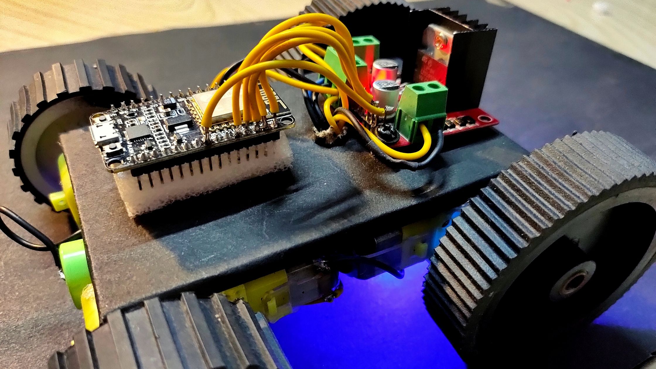
Circuit Connection of WiFi Controlled Robot Car
The first important thing is to program the ESP8266 NodeMCU. It is responsible for configuring through serial communication and also controlling the L298N motor driver module.
We are using ESP8266 NodeMCU here instead of Arduino. So the complexity of the circuit connection and coding is waived a little.
First, the inputs of the L298N motor driver module i.e. IN1, IN2, IN3 and IN4 are connected to digital pins D1, D2, D3 and D4 of the ESP8266 NodeMCU. And the enable pins ENA and ENB are connected to the D0 and D5 respectively.
Coming to the robot chassis, it has contained four geared motors. So, we need to connect the right two motors in parallel and connect them to the OUT1 and OUT2 terminals of the motor driver. Similarly, connect the left two motors to OUT3 and OUT4.
Preparing Software For WiFi Controlled Robot Car
Communication between devices and servers will be established when there is a proper dashboard present. For this project, we have used Blynk for controlling the WiFi robot.
To upload code to ESP8266 NodeMCU, we need Arduino IDE software.
First, open Arduino IDE software.
Go to File and select Preferences and paste the link “https://arduino.esp8266.com/stable/package_esp8266com_index.json” in Additional Board Manager URLs to add the ESP8266 board. Open Boards Manager from the Tools menu and type ESP8266 to install the ESP8266 platform. For programming the ESP8266 module, one unique identity is required from the Blynk software. That is Auth code. After connecting to a network this ID help to communicate the device with it. Connecting to the local WiFi network requires WiFi SSID and password.
Before compiling and loading the code to this module, we have to install the Adafruit Sensor Library, and Blynk Library.
To add these libraries to Arduino IDE, go to Sketch – Include Library – Add .zip Library – locate and install files.
Preparing Dashboard For WiFi Controlled Robot Car
After that, open the official Blynk app and create an account for yourself. After creating a new project, you will get the Auth token via your email.
Copy this Auth token and paste it into the appropriate fields of the Arduino ESP8266 code. After that, upload the Arduino IDE code to the NodeMCU and wait for connecting with the device on the network.
The next page will show a blank space to add buttons for the system. Tap on the blank space and choose the button option and add this. Again click on this and choose a virtual pin and select the desired pin which you include in your Arduino code. Then click OK and press back.
Continue with the same process with the others three. After that choose the slider button for speed control and choose their virtual pins. Finally, get back to the homepage and click on the play button on the upper right side. You can control then your devices through this Blynk app.
Working Principle of WiFi Controlled Robot Car
A simple project called WiFi Controlled Robot Car using ESP8266 NodeMCU is implemented here. Let me explain how this robot works.
First, upload the ESP8266 code after making the necessary connections and changes to the code. By opening the serial monitor of the Arduino IDE software, we can see the AT Commands that are being sent to the ESP8266 NodeMCU Module.
After connecting the ESP8266 module to WiFi, it will assign a static IP and also creates a server. Once the server is made, the ESP8266 module is waiting for connecting with a client.
Now, if you open the android application which we have downloaded, we can find a simple layout that consists of five buttons with names FORWARD, REVERSE, RIGHT, LEFT and SPEED.
By looking at these buttons, we can understand what each button does. Simply click on the button to perform that particular action. It is as simple as that.
Conclusion of WiFi Controlled Robot Car
A simple WiFi controlled robot car made in this project where a robotic car is controlled using a mobile application over a WiFi network.
Anyone can make this project with advanced features by integrating a camera and accessing the live feed on the application.
ESP8266 NodeMCU Code
#define BLYNK_PRINT Serial
#include <ESP8266WiFi.h>
#include <BlynkSimpleEsp8266.h>

//Motor PINs
#define ENA D0
#define IN1 D1
#define IN2 D2
#define IN3 D3
#define IN4 D4
#define ENB D5

bool forward = 0;
bool backward = 0;
bool left = 0;
bool right = 0;
int Speed;
char auth[] = ""; //Enter your Blynk auth token
char ssid[] = ""; //Enter your WIFI Name
char pass[] = ""; //Enter your WIFI Passowrd


void setup() {
  Serial.begin(9600);
  pinMode(ENA, OUTPUT);
  pinMode(IN1, OUTPUT);
  pinMode(IN2, OUTPUT);
  pinMode(IN3, OUTPUT);
  pinMode(IN4, OUTPUT);
  pinMode(ENB, OUTPUT);

  Blynk.begin(auth, ssid, pass);
}

BLYNK_WRITE(V0) {
  forward = param.asInt();
}

BLYNK_WRITE(V1) {
  backward = param.asInt();
}

BLYNK_WRITE(V2) {
  left = param.asInt();
}

BLYNK_WRITE(V3) {
  right = param.asInt();
}

BLYNK_WRITE(V4) {
  Speed = param.asInt();
}

void smartcar() {
  if (forward == 1) {
    carforward();
    Serial.println("carforward");
  } else if (backward == 1) {
    carbackward();
    Serial.println("carbackward");
  } else if (left == 1) {
    carturnleft();
    Serial.println("carfleft");
  } else if (right == 1) {
    carturnright();
    Serial.println("carright");
  } else if (forward == 0 && backward == 0 && left == 0 && right == 0) {
    carStop();
    Serial.println("carstop");
  }
}
void loop() {
  Blynk.run();
  smartcar();
}

void carforward() {
  analogWrite(ENA, Speed);
  analogWrite(ENB, Speed);
  digitalWrite(IN1, LOW);
  digitalWrite(IN2, HIGH);
  digitalWrite(IN3, HIGH);
  digitalWrite(IN4, LOW);
}
void carbackward() {
  analogWrite(ENA, Speed);
  analogWrite(ENB, Speed);
  digitalWrite(IN1, HIGH);
  digitalWrite(IN2, LOW);
  digitalWrite(IN3, LOW);
  digitalWrite(IN4, HIGH);
}
void carturnleft() {
  analogWrite(ENA, Speed);
  analogWrite(ENB, Speed);
  digitalWrite(IN1, HIGH);
  digitalWrite(IN2, LOW);
  digitalWrite(IN3, HIGH);
  digitalWrite(IN4, LOW);
}
void carturnright() {
  analogWrite(ENA, Speed);
  analogWrite(ENB, Speed);
  digitalWrite(IN1, LOW);
  digitalWrite(IN2, HIGH);
  digitalWrite(IN3, LOW);
  digitalWrite(IN4, HIGH);
}
void carStop() {
  digitalWrite(IN1, LOW);
  digitalWrite(IN2, LOW);
  digitalWrite(IN3, LOW);
  digitalWrite(IN4, LOW);
}


You can use two 3.7V li-ion batteries for powering up the whole system.
does this have to use a 12v battery? please explain a little why I can’t use a 3.7v or some variation?
Sir mere ko other projects banana seekhna Hai dikha dijie please sir
Yes I project working properly. After Few days, I am able to upload the output video.
Does this project actually work “properly’?????? There is no video-clip showing the working performance of this Robotic Car ! ! ! Looks like it could be performing with random errors just like when there are Bugs in the code (paying HiWi: taking wrong turns, stopping suddenly etc).
The reason I am asking this question is because the Node-MCU unit is inserted in some material which seems “Antistatic” foam hence all the pins would be connected together with very low resistances.
NOTE: Antistatic materials are used to store and transport CMOS electronic chips for not getting damaged from static charges because of its conducting properties.. You learn this in the 1st year of your Electronics Degree at any university in Australia and USA.