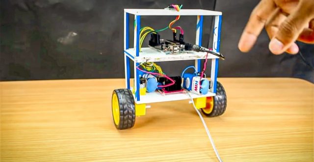
In this robotics project, we are going to make a self balancing robot using Arduino. In this, we can learn the balancing concept and how to control the motors. They have a wide range of applications, from entertainment to industrial automation.
Once I started to build this project, I realized that it is quite a bit challenging to build. There are so many things to consider for building this project like choosing motors, wheels, chassis, battery position and gyroscope sensor. After researching all criteria I chose some easy parts for building this project easily.
Here we use the MPU6050 accelerometer which interfaces with Arduino and sends some Analog signals to the Arduino on the x-axis, y-axis, and z-axis.
Must Read Arduino Bluetooth Controlled Car
What is Self Balancing Robot?
Self Balancing Robot is a two-wheeler automated robot that can balance itself from falling to the ground. This is similar to other typical two-wheeled self balancing robots, such as the Segway. Its function is to maintain balance using the motor’s axis movement of the wheels and body.
Types of self-balancing robots
There are several types of self balancing robots.
- One-wheeled balancing robots: These robots use a single wheel to balance. They generally have a compact design than two-wheeled robots.
- Two-wheeled balancing robots: These are the most common type of self-balancing robots, and they use inverted pendulum technology to maintain their balance.
- Three-wheeled balancing robots: These robots have three wheels and use the same techniques as two-wheeled robots to maintain their balance. They are more stable than two-wheeled robots but have a complex design.
Project
Circuit Diagram
Components Required
- Arduino
- Geared DC motors (x2)
- L298N Motor Driver Module
- MPU6050 Accelerometer
- Two Wheels (x2)
- 3.7V Lithium-Ion Battery (x4)
- Connecting Wires
- Foam Sheet
About Self Balancing Robot Project Parts
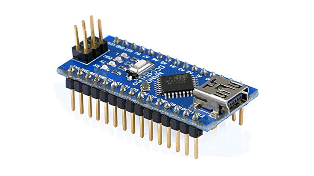
Arduino
The microcontroller that I have used here is Arduino Uno because it is simple to use. You can also use an Arduino Nano or Arduino Mini but I would recommend you stick with Arduino Uno since it does not need any breadboard for connection setup, so it can easily fit in a small chassis.
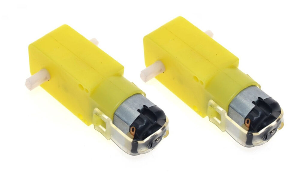
Motors
The best choice of motor that you can use for a self balancing robot, without a doubt will be a stepper motor. But To keep things simple I have used a DC-geared motor. Yes, it is not mandatory to have a stepper motor; the bot works fine with these cheap yellow-coloured DC geared motors as well.
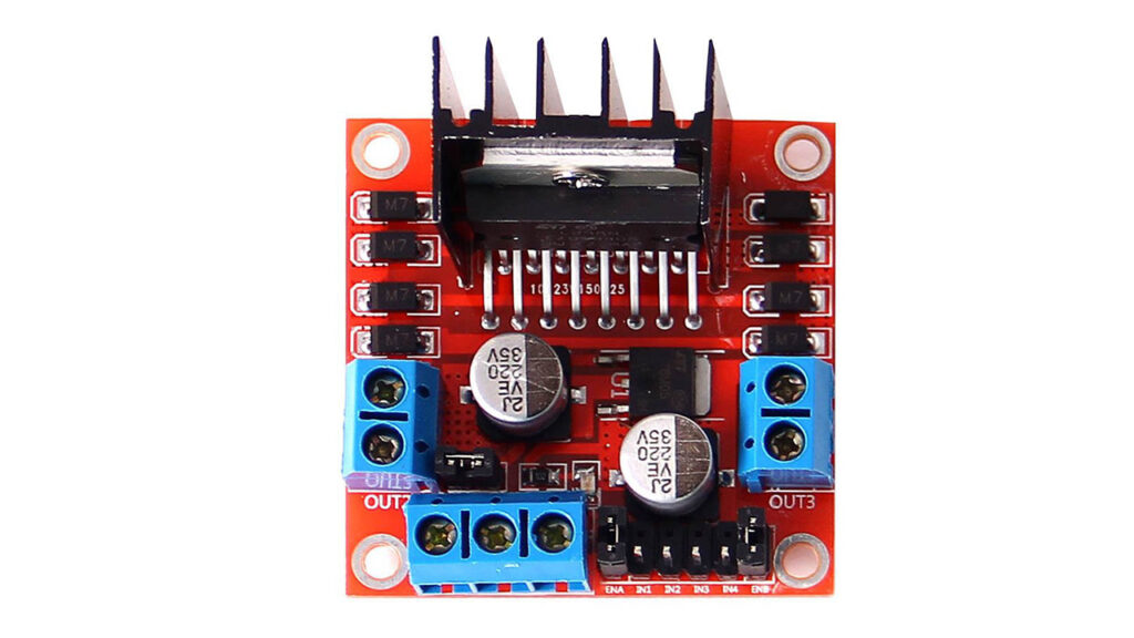
Motor Driver
If you have selected the DC geared motors then you can either use the L298N driver module or an L293D driver module. Both are similar in work. The Difference is that L298N is more powerful than L293D. But in that case, we can use any of them. I chose the L298N motor driver.
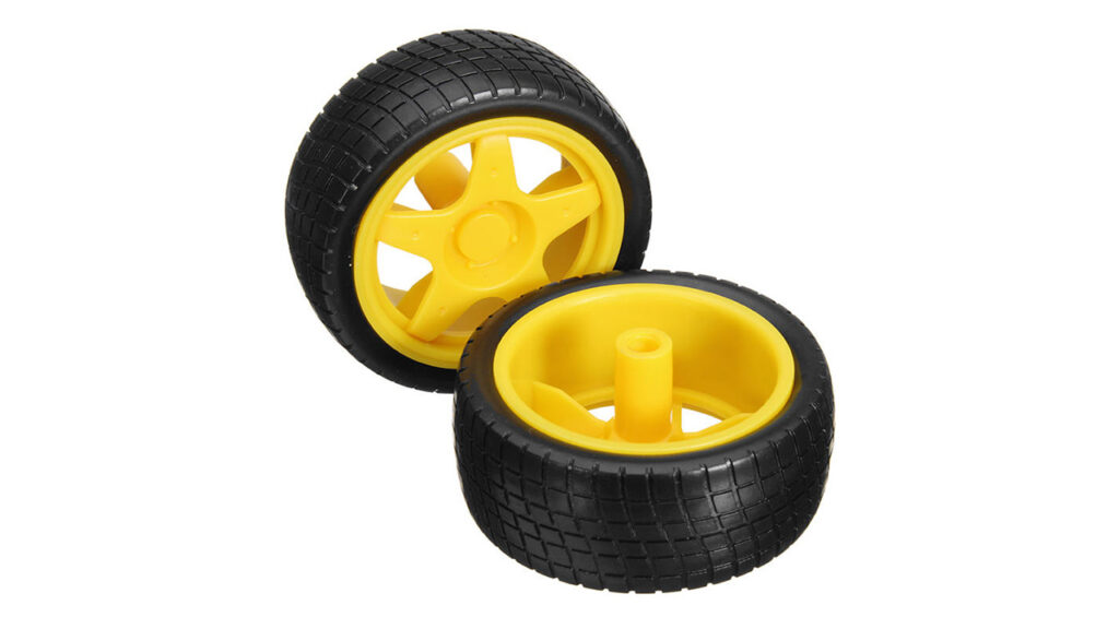
Wheels
I had a tough time figuring out that the problem was with my wheels. So make sure your wheels have a good grip over the floor you are using. Watch closely, your grip should never allow your wheels to skit on the floor.
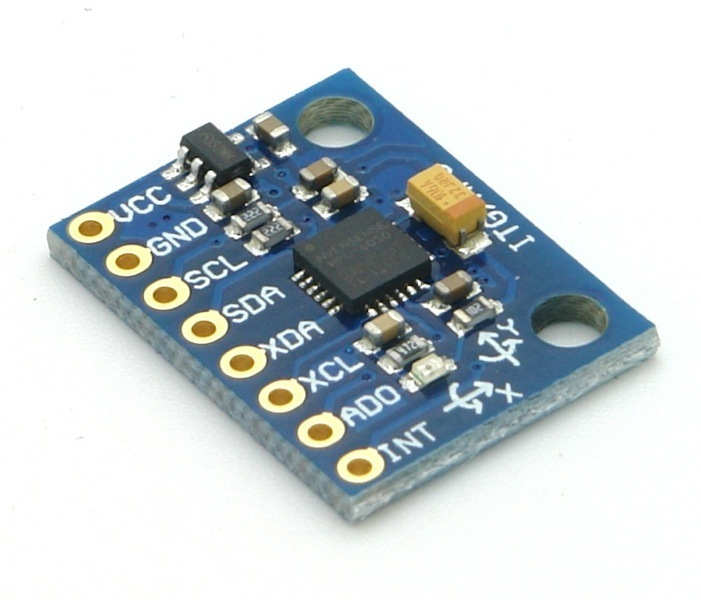
Accelerometer
The best choice of accelerometer and gyroscope sensor for this project is the MPU6050.
Steps to Assembly Self Balancing Robot Parts
Step 1: Assemble the Robot Chassis

The first step is to assemble the robot chassis using a premade robot kit or by building it from scratch. The chassis should be lightweight and sturdy with enough space to hold all the components.
Step 2: Connect the Motors to the Motor Driver
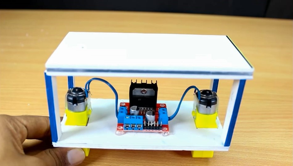
The next step is to connect the motors to the motor driver module. You need to connect both the positive and negative terminals of the dc motors to the motor driver module.
Step 3: Connect the Motor Driver to the Arduino
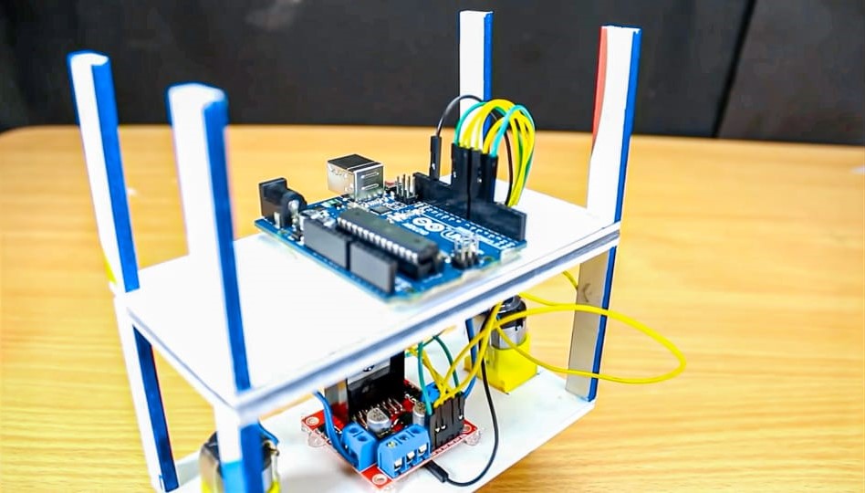
Connect the motor driver with the Arduino with the help of the circuit diagram given above. You need to connect the input pins of the motor driver to the digital pins of the Arduino.
Step 4: Connect the MPU6050 Accelerometer Sensor to the Arduino

The next step is to connect the MPU6050 accelerometer sensor to the Arduino. You need to connect the SDA and SCL pins of the MPU6050 to the corresponding pins of the Arduino which is shown on the circuit diagram.
Circuit Connection of Self Balancing Robot
Making the connections for this Self Balancing Robot using Arduino is pretty simple. We just have to interface the MPU6050 accelerometer with Arduino and connect the motors through the Motor Driver Module. The whole set-up is powered by a 9V battery.
The Arduino and the L298N Motor Driver Module are directly powered through the Vin pin and the 12V terminal respectively. The onboard regulator on the Arduino board will convert the input 9V to 5V and the ATmega IC and MPU6050 will be powered by it. The DC motors can run from voltage 5V to 12V. But we will be connecting the 9V positive wire from the battery to the 12V input terminal of the Motor Driver Module. This will make the motors operate with 9V.
The following connection chart of the self balancing robot will list how the MPU6050 and L298N Motor Driver Module are connected with Arduino.
- MPU6050 Vcc pin to +5V pin of Arduino Nano
- GND pin of Arduino Nano to MPU6050 ground pin
- Arduino Nano A5 pin to MPU6050 SCL pin
- MPU6050 SDA pin to A4 pin of Arduino Nano
- MPU6050 INT pin to D2 pin of Arduino Nano
- L298N IN1 pin to D6 pin of Arduino Nano
- IN2 pin to D9 pin of Arduino Nano
- IN3 pin to D10 pin of Arduino Nano
- IN4 pin to D11 pin of Arduino Nano
Working Principle of Self Balancing Robot
In this self balancing robot project, once you are ready with the hardware, you can upload the code to your Arduino board. Make sure the connections are proper since we are using a 9V battery, extreme caution is needed. So double-check for short circuits and ensure that the terminals won’t come into contact even if your robot experiences some small impacts. Power up your module and open your serial monitor, if your Arduino could communicate with MPU6050 successfully and if everything is working as expected you should see the following screen. If the robot is perfectly balanced, the value of output will be 0. The input value is the current value from the MPU6050 sensor.
During the initial stages of PID, I recommend leaving your Arduino cable connected to the robot so that you can easily monitor the values of input and output also it will be easy to correct and upload your program for Kp, Ki and Kd values.
Hope this helps to build your own self balancing robot.
Applications of Self Balancing Robot
Self-balancing robots have a wide range of applications, including:
- Entertainment: Self balancing robots are popular as toys and entertainment products, and they are often used in technical exhibitions and shows.
- Industrial Automation: Nowadays self balancing robots are used in industrial automation for transporting goods, monitoring inventory, and performing other tasks.
- Personal Transportation: Self balancing robots can be used as personal transportation, and they are replacing traditional bicycles and electric scooters in recent times.
Arduino Source Code for Self Balancing Robot
For establishing this code of self balancing robot, we need two libraries. The library is developed by Br3ttb and Jrowberg respectively. Before proceeding download their libraries from the following link and add them to your Arduino lib directory.
Next the Arduino code for the self balancing robot
1 2 3 4 5 6 7 8 9 10 11 12 13 14 15 16 17 18 19 20 21 22 23 24 25 26 27 28 29 30 31 32 33 34 35 36 37 38 39 40 41 42 43 44 45 46 47 48 49 50 51 52 53 54 55 56 57 58 59 60 61 62 63 64 65 66 67 68 69 70 71 72 73 74 75 76 77 78 79 80 81 82 83 84 85 86 87 88 89 90 91 92 93 94 95 96 97 98 99 100 101 102 103 104 105 106 107 108 109 110 111 112 113 114 115 116 117 118 119 120 121 122 123 124 125 126 127 128 129 130 131 132 133 134 135 136 137 138 139 140 141 142 143 144 145 146 147 148 149 150 151 152 153 154 155 156 157 158 159 160 161 162 163 164 | #include "I2Cdev.h" #include <PID_v1.h> #include "MPU6050_6Axis_MotionApps20.h" MPU6050 mpu; // MPU control/status vars bool dmpReady = false; // set true if DMP init was successful uint8_t mpuIntStatus; // holds actual interrupt status byte from MPU uint8_t devStatus; // return status after each device operation (0 = success, !0 = error) uint16_t packetSize; // expected DMP packet size (default is 42 bytes) uint16_t fifoCount; // count of all bytes currently in FIFO uint8_t fifoBuffer[64]; // FIFO storage buffer // orientation/motion vars Quaternion q; // [w, x, y, z] quaternion container VectorFloat gravity; // [x, y, z] gravity vector float ypr[3]; // [yaw, pitch, roll] yaw/pitch/roll container and gravity vector /*****Tune these 4 values for your ROBOT*****/ double setpoint= 176; //set the value when the robot is perpendicular to ground using serial monitor. //Read the project documentation on circuitdiagrams.in to learn how to set these values double Kp = 21; //Set this first double Kd = 0.8; //Set this secound double Ki = 140; //Set this third /******End of values setting*********/ double input, output; PID pid(&input, &output, &setpoint, Kp, Ki, Kd, DIRECT); volatile bool mpuInterrupt = false; // indicates whether MPU interrupt pin has gone high void dmpDataReady() { mpuInterrupt = true; } void setup() { Serial.begin(115200); // initialize device Serial.println(F("Initializing I2C devices...")); mpu.initialize(); // verify connection Serial.println(F("Testing device connections...")); Serial.println(mpu.testConnection() ? F("MPU6050 connection successful") : F("MPU6050 connection failed")); // load and configure the DMP devStatus = mpu.dmpInitialize(); // supply your own gyro offsets here, scaled for min sensitivity mpu.setXGyroOffset(220); mpu.setYGyroOffset(76); mpu.setZGyroOffset(-85); mpu.setZAccelOffset(1688); // make sure it worked (returns 0 if so) if (devStatus == 0) { // turn on the DMP, now that it's ready Serial.println(F("Enabling DMP...")); mpu.setDMPEnabled(true); // enable Arduino interrupt detection Serial.println(F("Enabling interrupt detection (Arduino external interrupt 0)...")); attachInterrupt(0, dmpDataReady, RISING); mpuIntStatus = mpu.getIntStatus(); // set our DMP Ready flag so the main loop() function knows it's okay to use it Serial.println(F("DMP ready! Waiting for first interrupt...")); dmpReady = true; // get expected DMP packet size for later comparison packetSize = mpu.dmpGetFIFOPacketSize(); //setup PID pid.SetMode(AUTOMATIC); pid.SetSampleTime(10); pid.SetOutputLimits(-255, 255); } else { // ERROR! // 1 = initial memory load failed // 2 = DMP configuration updates failed // (if it's going to break, usually the code will be 1) Serial.print(F("DMP Initialization failed (code ")); Serial.print(devStatus); Serial.println(F(")")); } //Initialise the Motor outpu pins pinMode (6, OUTPUT); pinMode (9, OUTPUT); pinMode (10, OUTPUT); pinMode (11, OUTPUT); //By default turn off both the motors analogWrite(6,LOW); analogWrite(9,LOW); analogWrite(10,LOW); analogWrite(11,LOW); } void loop() { // if programming failed, don't try to do anything if (!dmpReady) return; // wait for MPU interrupt or extra packet(s) available while (!mpuInterrupt && fifoCount < packetSize) { //no mpu data - performing PID calculations and output to motors pid.Compute(); //Print the value of Input and Output on serial monitor to check how it is working. Serial.print(input); Serial.print(" =>"); Serial.println(output); if (input>150 && input<200){//If the Bot is falling if (output>0) //Falling towards front Forward(); //Rotate the wheels forward else if (output<0) //Falling towards back Reverse(); //Rotate the wheels backward } else //If Robot not falling Stop(); //Hold the wheels still } // reset interrupt flag and get INT_STATUS byte mpuInterrupt = false; mpuIntStatus = mpu.getIntStatus(); // get current FIFO count fifoCount = mpu.getFIFOCount(); // check for overflow (this should never happen unless our code is too inefficient) if ((mpuIntStatus & 0x10) || fifoCount == 1024) { // reset so we can continue cleanly mpu.resetFIFO(); Serial.println(F("FIFO overflow!")); // otherwise, check for DMP data ready interrupt (this should happen frequently) } else if (mpuIntStatus & 0x02) { // wait for correct available data length, should be a VERY short wait while (fifoCount < packetSize) fifoCount = mpu.getFIFOCount(); // read a packet from FIFO mpu.getFIFOBytes(fifoBuffer, packetSize); // track FIFO count here in case there is > 1 packet available // (this lets us immediately read more without waiting for an interrupt) fifoCount -= packetSize; mpu.dmpGetQuaternion(&q, fifoBuffer); //get value for q mpu.dmpGetGravity(&gravity, &q); //get value for gravity mpu.dmpGetYawPitchRoll(ypr, &q, &gravity); //get value for ypr input = ypr[1] * 180/M_PI + 180; } } void Forward() //Code to rotate the wheel forward { analogWrite(6,output); analogWrite(9,0); analogWrite(10,output); analogWrite(11,0); Serial.print("F"); //Debugging information } void Reverse() //Code to rotate the wheel Backward { analogWrite(6,0); analogWrite(9,output*-1); analogWrite(10,0); analogWrite(11,output*-1); Serial.print("R"); } void Stop() //Code to stop both the wheels { analogWrite(6,0); analogWrite(9,0); analogWrite(10,0); analogWrite(11,0); Serial.print("S"); } |
Conclusion
Self balancing robot is an amazing robotic technology that has a wide range of applications. From entertainment to industrial applications, these robots have the potential to revolutionize many industries. We hope that this project has given you a comprehensive guide to self balancing robots and their working principle.
FAQs
Self balancing robot uses an accelerometer sensor to measure the robot’s angle and position, and a control system to adjust the motors and maintain its balance. The control system uses feedback loops to continuously adjust the robot’s position and keep it working.
Self balancing robots have a variety of practical applications, like education, research, entertainment, and transportation. They can be used for tasks such as carrying small loads, navigating difficult terrain, and performing precise movements.
Yes, there are many resources available for building your own self balancing robot, including online tutorials, kits, and open-source software.
The cost of a self balancing robot can vary depending on its complexity and features. Some basic models can be built for a few dollars, while more advanced models can cost thousands of dollars.

Como se conectaria todo con un arduino uno y un giroscopio gy-61
Is it really working?