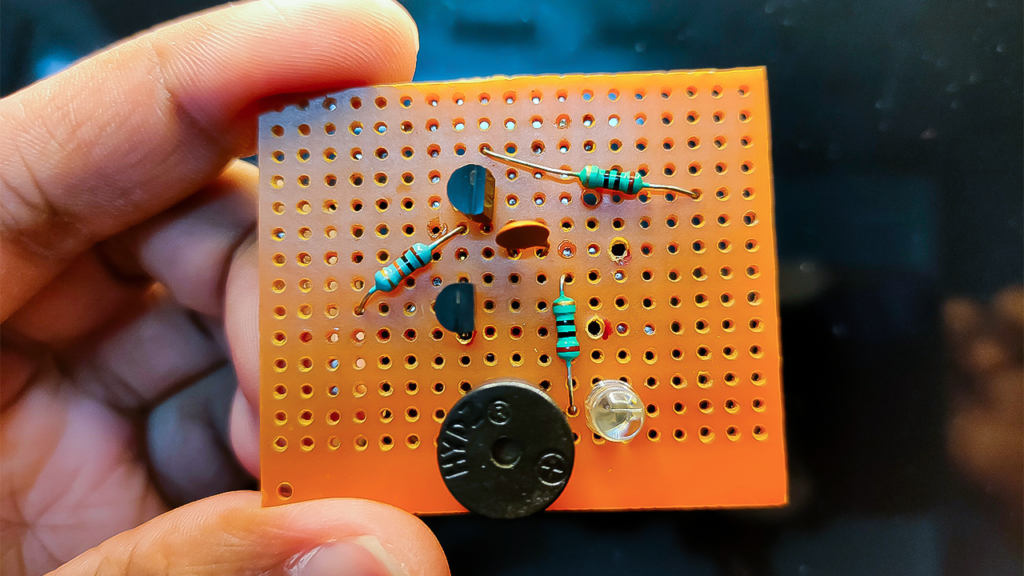
In this tutorial, I will show you a rain alarm circuit with an easy tutorial. This is very useful for home use because it alerts us whenever rainwater falls on the two probes which are connected to NPN and PNP transistors, the rain alarm circuit will turn on and the buzzer will start to beep.
Must Read Small Electronics Projects
Project
Circuit Diagram
Components Required
- BC548
- BC558
- 10 KΩ Resistor
- 330 KΩ Resistor
- 0.01uF Ceramic Capacitor
- Buzzer
- Connecting Wires
- 9V Battery
- Breadboard
Circuit Connection
To build the circuit connection of the rain alarm circuit first, we need to place the transistors (i.e., BC548 & BC558) on the breadboard.
Now it’s time to connect a 330 KΩ resistor in the emitter terminal of the PNP transistor and the other end of the resistor is connected to an open-ended wire.
Connect a 0.01uF capacitor and a 10 KΩ resistor on the collector of the PNP transistor. We have used a resistor and a capacitor in series so that it causes the first transistor to turn on and off followed by the second.
Now, in order to indicate the rain, we are connecting a buzzer. The positive side is connected to the collector of the PNP transistor and the negative side is connected to the emitter of the NPN transistor. Here the collector of the BC548 transistor is connected to the base of the BC558 transistor.
Here we need a 9V power supply. Connect the positive end to the emitter of the PNP transistor and the negative to the emitter of the NPN transistor. And also connect a probe to the base of the NPN transistor.
Working Principle of Rain Alarm
We all know that water is a decent conduit of power. By this principle of the rain alarm circuit, the contact between two wires takes place and a current starts flowing towards the base of the NPN transistor. Since the collector of the NPN transistor is connected to the base of the PNP transistor. When the NPN transistor starts to conduct, the PNP transistor will also start conducting.
Thus the whole circuit will turn on and the buzzer starts to beeping.


Dear Dhiraj, very good question from your side. Actually this circuit having one resistance and one capacitor is called as oscillation circuit which changes the frequency of buzzer sound i.e. tone of buzzer.
Resistor R2 has been used to control the transistor’s base current. Rain sensor should be kept at 30 to 40 degree from the ground, so that water cannot stay on it for a long time, this will prevent the alarm from going on for a long time. And the C1 capacitor is used to change the frequency of the buzzer sound.
Is this circuit correct? If yes then what is the use of resistor and a capacitor in series between npn base and buzzer.can you tell what are those component doing in the circuit or its function.