By going to shrinkify Arduino projects are not possible sometimes according to their sizes. Even Arduino Nano also failed. Then comes a little chip to fulfil our expectation i.e. ATtiny85 Microcontroller. It works like a normal Arduino without any crystal oscillator or anything.
The ATtiny series is one of the smallest well-known microcontrollers in the AVR market. This tiny microcontroller supports many of the libraries in the Arduino IDE software. It consists of 8-pins and an 8-bit AVR microcontroller. Being too small, it needs very less power consumption which is great for portable projects with low requirements.
But the programming this ic is a little bit difficult. Considering Arduino Uno/Nano, it is easy because of the USB to TTL serial adapter and crystal oscillator. For this reason, we need to connect both Arduino and ATtiny85 IC using the master-slave method for programming Arduino as ISP. But we overcome this problem in this article.
This project will help us program every type of ATtiny chip using only a USB port and Digispark.
Must Read Top Arduino Projects For Engineering
Project

What is Digispark?
Digispark is an ATtiny85-based microcontroller development board i.e. cheaper, and smaller than other Arduino boards. Its coding is similar to other ones. It can communicate with computers through USB. But for that, we need a Digispark USB driver.
About ATtiny85 Microcontroller
ATtiny85 is a high-performance 8-bit Atmel microcontroller that has an advanced RISC Architecture. It has 8KB ISP flash memory, 512 Byte EEPROM, 512-Byte SRAM, 6 general-purpose I/O lines, 32 general-purpose working registers, one 8-bit timer/counter with compare modes, one 8-bit high-speed timer/counter, USI, internal and external Interrupts, 4-channel 10-bit A-D converter, programmable watchdog timer with internal oscillator, three software selectable power saving modes, and debugWIRE for on-chip debugging.
Pinout Configuration of ATtiny85 Microcontroller
| Pin No. | Pin Name | Description |
|---|---|---|
| 1 | PB5(PCINT5/ADC0/dW) | PCINT5: Pin Change Interrupt 0, Source5 RESET: Reset Pin ADC0: ADC Input Channel 0 dW: debug WIRE I/O. |
| 2 | PB3(PCINT3/XTAL1/CLKI/ADC3) | PCINT3: Pin Change Interrupt 0, Source3 XTAL1: Crystal Oscillator Pin1 CLKI: External Clock Input ADC3: ADC Input Channel 3. |
| 3 | PB4(PCINT4/XTAL2/CLKO/OC1B/ADC2) | PCINT4: Pin Change Interrupt 0, Source 4 XTAL2: Crystal Oscillator Pin 2 CLKO: System Clock Output OC1B: Timer/Counter1 Compare Match B Output ADC2: ADC Input Channel 2. |
| 4 | GND | Ground. |
| 5 | PB0(MOSI/DI/SDA/AIN0/OC0A/AREF/ PCINT0) | MOSI: SPI Master Data Output / Slave Data Input DI: USI Data Input (Three Wire Mode) SDA: USI Data Input (Two Wire Mode) AIN0: Analog Comparator, Positive Input OC0A: Timer/Counter0 Compare Match A output AREF: External Analog Reference PCINT0: Pin Change Interrupt 0, Source 0. |
| 6 | PB1(MISO/D0/AIN1/OC0B/OC1A/ PCINT1) | MISO: SPI Master Data Input / Slave Data Output DO: USI Data Output (Three Wire Mode) AIN1: Analog Comparator, Negative Input OC0B: Timer/Counter0 Compare Match B Output OC1A: Timer/Counter1 Compare Match A Output PCINT1: Pin Change Interrupt 0, Source 1. |
| 7 | PB2(SCK/USCK/SCL/ADC1/T0/INT0/ PCINT2) | SCK: Serial Clock Input USCK: USI Clock (Three Wire Mode) SCL: USI Clock (Two Wire Mode) ADC1: ADC Input Channel 1 T0: Timer/Counter0 Clock Source INT0: External Interrupt 0 Input PCINT2: Pin Change Interrupt 0, Source 2. |
| 8 | VCC | Supply Voltage. |
Flashing Bootloader On ATtiny85 Microcontroller Using Arduino
At first, we need to upload the bootloader into the ATtiny85 using an Arduino board. Otherwise, we can’t upload any code into the ATtiny85 chip without Arduino. After this process, we don’t need any Arduino to upload code every time. The bootloader is a special type of program that has to be programmed.
One of the easiest ways to upload program data into the ATtiny85 microcontroller is through a bootloader. The bootloader is set up on the MCU, performs all the incoming instructions, and writes a new program to the memory of the microcontroller. Flashing a bootloader on a microcontroller removes the need for external hardware components to program the microcontroller. We will be able to program it directly through a USB plug.
The bootloader is a pre-programmed driver code on Digispark and allows ATtiny85 to act as a USB drive. So it can be programmed by Arduino IDE. We also need to flash the Digispark attiny85 bootloader on ATtiny85.
Step by step process to flash the bootloader is described below:
Configuring Arduino as ISP

First, we require an ISP (In-System Programming) to be programmed. For that, we need to configure Arduino as ISP to act as a programmer for the ATtiny85 microcontroller. Now connect the Arduino to the computer and open the Arduino IDE software. After that, click on File > Example > ArduinoISP and upload the Arduino ISP code to the Arduino.
Connection for Flashing The Bootloader on Arduino

The complete circuit connection is shown in the above picture. Do as it is. A 10uF/16V capacitor is connected between the reset and ground pin of the Arduino for smoothening the process.
| ATtiny85 | Arduino |
|---|---|
| VCC | 5V |
| GND | GND |
| PIN2 | D13 |
| PIN1 | D12 |
| PIN0 | D11 |
| Reset | D10 |
Burning Bootloader Into The ATtiny85
Now plug in the Arduino to the computer through a cable and open Arduino IDE software. Find the exact COM port for the Arduino in the tools section. In my case, it’s “COM5”. After that, download the ATtiny85 Bootloader file from the given link.
Open the “Burn_AT85_bootloader.bat” file and change the COM port number to “PCOM5”. Save the changes and copy-paste the edited “Burn_AT85_bootloader.bat” and “ATtiny85.hex” files into the Arduino IDE root folder (C:\Program Files (x86)\Arduino).
After that, right-click on “Burn_AT85_bootloader.bat” and select “Run as Admin”. It takes approx 6 seconds to flash the bootloader. If all are correct, we will receive a message “Avrdude done. Thank you. Press any key to continue…”.
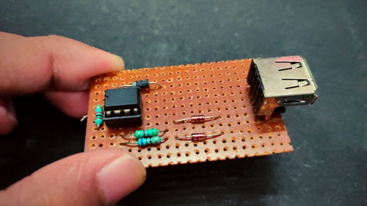
Now the Bootloader is completely installed into the ATtiny85 microcontroller. It’s time to connect the USB with ATtiny85 to program it directly. The connection for programming ATtiny85 through USB is shown below:
Circuit Diagram

Components Required
- Arduino UNO/Nano ( Only for the bootloader)
- ATtiny85 chip
- 47 Resistor (x2)
- 1K Resistor (x2)
- 3.3V Zener Diode (x2)
- 1N5819 Diode
- 8-Pin IC Base
- USB A-Type Male
Install Digispark Driver for ATtiny85 Microcontroller
We need Digispark Driver to program the ATtiny85 microcontroller using USB. Download and extract the zip file and double-click on the “DPinst64.exe” file to install the drivers on the computer.
Once the drivers are successfully installed on the computer, plug in the ATtiny85 board to the computer’s USB port. Next, we need to go to Device Manager on Windows and the ATtiny85 device will be visible with the name “libusb-win32 devices” as “Digispark Bootloader”. If you can’t find ‘libusb-win32 devices’ on the Device Manager, then just click to view and click on ‘Show hidden Devices’. The problem will be solved.
Now come to program the ATtiny85 board with Arduino IDE software. First, we need to install Digispark board support to Arduino IDE. To do that, go to File > Preferences and add the below link in the Additional Boards Manager URLs and click ‘OK.’
http://digistump.com/package_digistump_index.json
After that, go to tools > Board > Board Manager and search for ‘Digistump AVR’ and install the latest version. That’s it.
Now, go to file > Examples > Basics and open the Blink example. Change the pin number from LED_BUILTIN to 0. Now go to Tools > Board and select the “Digispark (16mhz)” board. Then click on the upload button in Arduino IDE.
Once the code is uploaded to the ATtiny85 microcontroller, the LED connected to ATtiny85 will start blinking.
ATtiny85 Code
// the setup function runs once when you press reset or power the board
void setup() {
  // initialize digital pin LED_BUILTIN as an output.
  pinMode(0, OUTPUT);
}
// the loop function runs over and over again forever
void loop() {
  digitalWrite(LED_BUILTIN, HIGH);   // turn the LED on (HIGH is the voltage level)
  delay(1000);                       // wait for a second
  digitalWrite(LED_BUILTIN, LOW);    // turn the LED off by making the voltage LOW
  delay(1000);                       // wait for a second
}


There’s something very comforting about your writing. It’s thoughtful and gentle, yet still rich with insight.
Why d1 In5819 is reversed, how to get VCC voltage ATtiny 85 ? thanks.