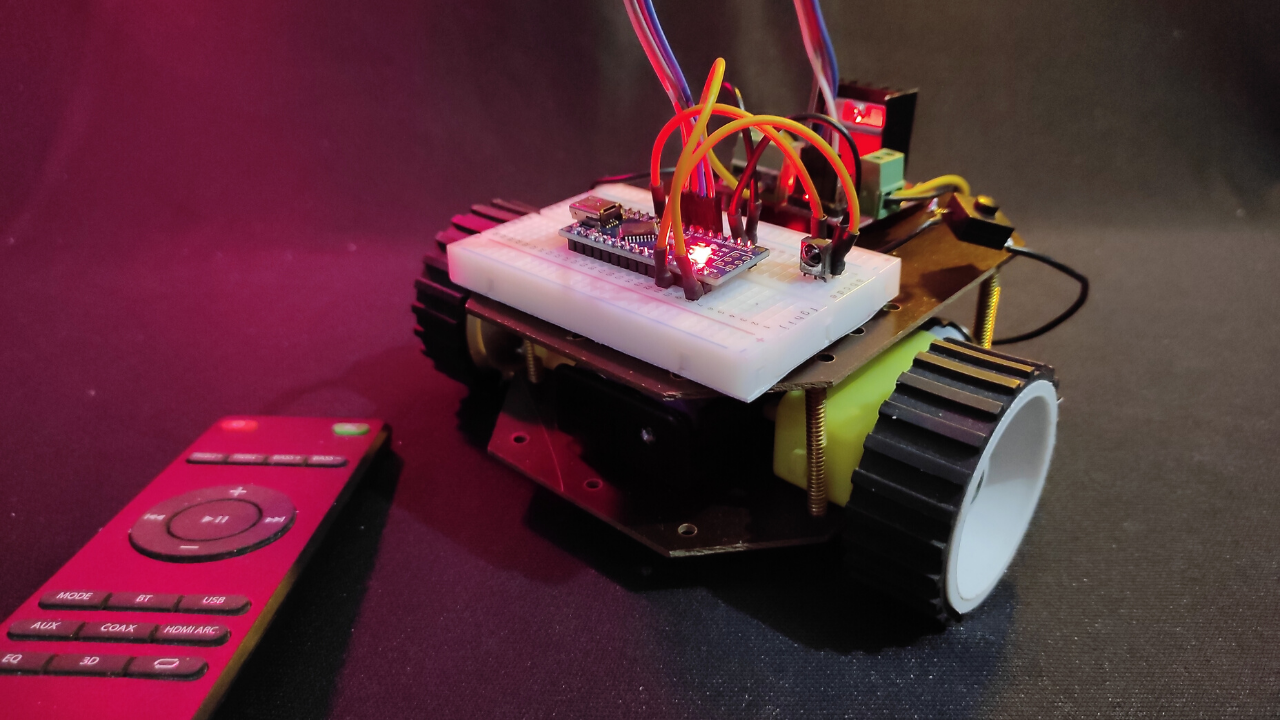
Remote control automation is very frequent in those days. We can see remote control appliances, locks, garage doors etc. The term RC has a dual meaning. One is remote control and the other is radio control. The remote control car uses an IR sensor. In this project, we are going to build an IR Remote Control Car using Arduino.
Here we use a three-pin infrared receiver to build this project. Also, we will show you how to control this car with all types of IR remotes. This IR remote control car can be operated wirelessly through remote keys. To do this, we use the TSOP1738 three-pin infrared receiver and Arduino Nano.
Principle Behind IR Remote Control Car
The principle behind this project is to send infrared modulated signals to the IR receiver. TSOP1738 works here as an infrared receiver. The TSOP1738 IR receiver receives the modulated signal and demodulates it into the Arduino. Then the demodulated signal has some noise that should be filtered. After this, the input signal is extracted. The main part of this project is decoding the remote keys in hex form.
Project

Circuit Diagrams

Components Required
- Arduino Nano
- TSOP1738 IR Receiver
- L298N Motor Driver
- Gear Motors (x2)
- Wheel (x2)
- 3.7V Li-Ion Battery (x2)
- Li-Ion Battery holder
- Chassis
About Parts of IR Remote Control Car
Arduino

For the compact build, I choose Arduino Nano despite Arduino UNO. Arduino Nano is a small, flexible microcontroller board using an Atmega328p chip. It can also use as a substitute for UNO. All the functions are the same in these two boards. The size of its PCB is 18×45 mm. The clock speed is 16Mhz. Its input voltage is 5-12V. There are 30 pins including power pins, data pins, analog pins, serial pins on this board.
TSOP1738 IR Receiver

This is a type of IR receiver which has an inbuilt amplifier. It acts as a switch and converter. TSOP1738 has three pins, which are GND, VSS, Output. Its operating frequency is 38KHz.
Dual Bridge L298N Motor Driver

L298N is a dual channel H-bridge motor driver. It can control four DC motors at the same time. The range of the voltage that can be used with it is 5V to 35V.
Decoding Method of Remote keys Using TSOP1738 IR Receiver

Connect the digital pin 2 of the Arduino with the output pin of TSOP1738. Then you get the IR remote signal. Now download the IR Remote library and go to the Arduino IDE → Sketch → Include Library → Add.ZIP Library. Then choose the right library and click that’s it. After uploading to code to Arduino, open the 9600 baud rate serial terminal to see the result.


Now point the IR remote to the IR receiver and press a button. You can see a hex value when you press the button. Remember this hex value or copy it. After some time repeat this and check the hex value remains the same.
/* IRremote:
IRrecvDemo - demonstrates receiving IR codes with IRrecv
An IR detector/demodulator must be connected to the input RECV_PIN.
Version 0.1 July, 2009
Copyright 2009 Ken Shirriff * http://arcfn.com
*/
#include <IRremote.h>
int RECV_PIN = 2;
IRrecv irrecv(RECV_PIN);
decode_results results;
void setup()
{
  Serial.begin(9600);
  irrecv.enableIRIn(); // Start the receiver
}
void loop() {
  if (irrecv.decode(&results)) {
    Serial.println(results.value, HEX);

    irrecv.resume(); // Receive the next value
  }
}Output of the Decoded IR Signals

| Remote Buttons | Hex Code |
|---|---|
| Forward (+) | 0x807F8877 |
| Left (←) | 0x807F906F |
| Backward (-) | 0x807F28D7 |
| Right (→) | 0x807F10EF |
Circuit and Working Principle of IR Remote Control Car
The connection between Arduino and TSOP1738 is quite easy. You have to connect the VSS pin of the TSOP1738 with the 5V pin and connect the ground pin with the ground pin of the Arduino. At last, connect the output pin of the TSOP1738 with the digital pin 11 of the Arduino. You can use any type of IR remote using this method.
To control this car, we need five buttons. These five buttons are used here to control the forward, Left, stop, right and backward of the remote control car respectively.
From the table, you can see the hex code with the function of these buttons. These codes will be sent via IR remote transmitter to the TSOP1738 IR receiver. So we need these codes while writing the program in the Arduino IDE.
When you press one of those buttons, Arduino matches it from the table. If code matched, Arduino takes the action of the particular button you pressed.
Arduino Code for IR Remote Control Car
#include <IRremote.h>
#include "pins_arduino.h"
int RECV_PIN = 3;   // Pin should be a PWM pin
IRrecv irrecv(RECV_PIN);
decode_results results;
void setup()
{
  irrecv.enableIRIn(); // Start the receiver
  pinMode(6,OUTPUT);
  pinMode(5,OUTPUT);
  pinMode(4,OUTPUT);
  pinMode(3,OUTPUT);
}
void loop() {
  if (irrecv.decode(&results))
  {
      switch(results.value)
      {
        case 0x807F8877:    //Serial.println("Forward"); // Volume Up Button
                         digitalWrite(6,LOW);
                         digitalWrite(5,HIGH);
                         digitalWrite(4,LOW);
                         digitalWrite(3,HIGH);
                         break;
        case 0x807F10EF:   //Serial.println("Backward"); // Volume Down Button
                         digitalWrite(6,HIGH);
                         digitalWrite(5,LOW);
                         digitalWrite(4,LOW);
                         digitalWrite(3,HIGH);
                         break;
        case 0x807F7A85:  //Serial.println("Stop"); // Pause Button
                         digitalWrite(6,HIGH);
                         digitalWrite(5,HIGH);
                         digitalWrite(4,HIGH);
                         digitalWrite(3,HIGH);
                         break;
        case 0x807F906F:  //Serial.println("Left"); // Previous Button
                         digitalWrite(6,LOW);
                         digitalWrite(5,HIGH);
                         digitalWrite(4,HIGH);
                         digitalWrite(3,LOW);
                         break;
        case 0x807F28D7:  //Serial.println("Right"); // Next Button
                         digitalWrite(6,HIGH);
                         digitalWrite(5,LOW);
                         digitalWrite(4,HIGH);
                         digitalWrite(3,LOW);
                         break;
      }
    irrecv.resume();      // Receive the next value
  }
}


Can we use indicator and horn also?
Nice project