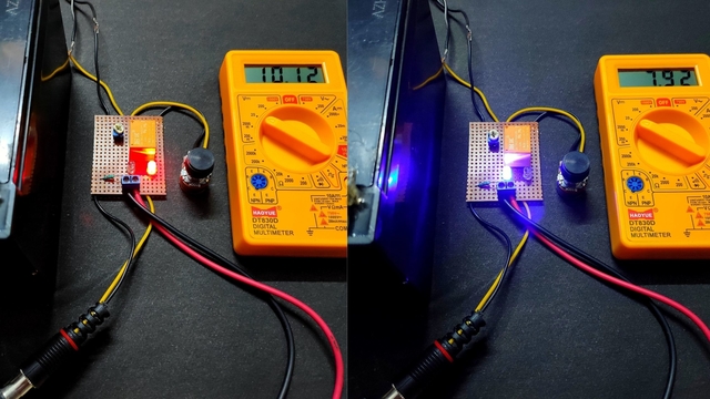
In this project, I will be going to show you a 1.2V to 12V variable auto-cut-off battery charger using a relay. When the battery level is below the maximum threshold voltage level, the charger starts to charge. When it gets its maximum voltage which is set, then the variable battery charger circuit will automatically cut the charging from the battery. Thus it prevents overcharging of the battery. It is used in many electronics projects for hobbyists.
Here are the full details of how a variable automatic battery charger can be built using a 12V relay and LM317 ic. It can be used in many electronics projects.
Must Read Full Wave Rectifier
Principle Behind Automatic Battery Charger
A battery works by converting its stored chemical energy into electrical energy. Once the electrolyte of the battery is used, it needs to be recharged. A battery charger is a device that can provide DC current to the battery to restore the electrolyte. So when all the electrolytes of the battery are restored, its current supply should stop.
Project

Circuit Diagram
Components Required
- 15-0 1A Step-Down Transformer
- LM317 Voltage Regulator
- 5 Ampere Bridge Rectifier
- 12V Relay
- 220Ω Resistor
- 1KΩ Resistor
- 1000uF/35V Electrolyte Capacitor
- LED (Green, Red)
- 20KΩ Preset (x2)
- Double-Sided Prototype Board
- Connection Wire
- 12V Battery
Circuit Connection
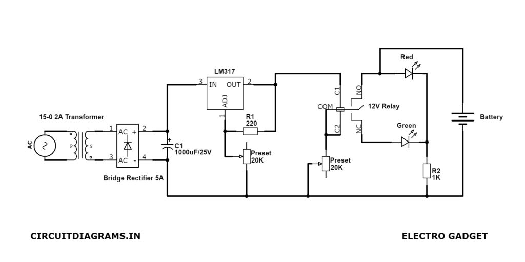
In this automatic variable battery charger circuit, a 15-0 1A step-down transformer is used. The main AC voltage 220V, 50Hz is connected to the primary part of the transformer.
The output of the transformer i.e. from the secondary part is connected between the diodes D1 and D2 and diodes D3 and D4. Here diodes D1, D2, D3, and D4 are used to convert the AC voltage to the pulsating DC voltage. This is a rectification process. A 1000uF/35V electrolytic capacitor is connected across the pulsating DC voltage to remove the unwanted ripples.
Thus we can get an unregulated DC voltage. This unregulated DC voltage needs to be regulated by using the LM317 voltage regulator to drive a regulated DC voltage.
The output voltage from the voltage regulator can be regulated from 1.2V to 37V and the maximum output current from this IC is 1.5A. The output voltage of the voltage regulator has operated by a preset whose value is 20KΩ which is connected to the adjustable pin of the LM317 ic. A 220Ω feedback resistor is connected between the adjustable pin and output pin of the LM317 ic.
The output of the LM317 voltage regulator is applied to a 12V relay module. Here we join the common terminal and one of the coil terminals together. Then it is directly pointed to the output terminal of the regulator ic. One of the terminals of another 20KΩ potentiometer is connected to another terminal of the relay coil.
After that, we connect the normally open terminal to the anode of the red LED. Another closed terminal to the anode of the green LED for indication purposes. And these two LED cathode terminals are connected to the ground through a 1KΩ resistor.
When it gets full charge, the relay which is connected to the circuit will not conduct the current flow. So all the current flow through the circuit will be grounded.
In this automatic battery charger circuit, the red LED indicates the charging of the battery and the green LED indicates the full charge.
Must Read LM317 Variable Voltage Power Supply
Working Principle of Automatic Battery Charger
When the battery level is getting low, then the current is flowing from the LM317 IC through the relay to the battery. At this point, the red LED will be indicating that this is in charging mode.
When the battery level reaches the maximum threshold voltage i.e. 13.7V, then the current flowing to the battery is stopped. Then the close terminal flows the current to the ground. It is indicated by a green LED. Thus the whole circuit is working respectively.
The whole charging process of the circuit is a combination of charging, stabilizing, and terminating. Charging and discharging rates of the batteries are given as C-rate (Charge Rate). It is the measure of the rate at which the battery is charged or discharged with respect to its capacity (Ah). As an example, a fully charged battery of 7Ah will discharge at a 7A rate, then it will take time to get fully charged.
Applications of Automatic Battery Charger
This automatic battery charger can use for all types of lead acid batteries to charge.
It can also be used as a DC variable power source.
FAQ
A battery charger is worked by converting AC voltage to DC voltage. Once the electrolyte of the battery is used, it needs to be recharged. A battery charger is a device that can provide DC current to the battery to restore the electrolyte. So when all the electrolytes of the battery are restored, its current supply should stop.
There are three types of battery chargers that are constant voltage, constant current and a combination of constant voltage/constant current.
A battery charger circuit consists of a rectifier circuit, a ripple filter circuit, a voltage regulation circuit and a cut-off voltage circuit.
