Almost all of us have expensive or cheap music systems in our homes. Most musical concerts, festivals and nightclubs are accompanied by fancy disco lights to show visual effects according to music rhythm. So, I planned to build my own Audio Spectrum Visualizer that reacts to music or audio. For this, I used Arduino Nano as the main heart of this project, and 32×8 Dot Matrix Display, and a sound sensor.
The individual LEDs on the Dot Matrix Display will react according to the Analog audio signals that Arduino Nano receives through the sound sensor that is connected to its Analog pin. Arduino has a built-in ADC (Analog to Digital converter) input pin which can receive the Analog audio signals from the sound sensor and convert it to a digital signals.
Some days ago I have built a Music Reactive LED System Using ESP32 and WLED. You can also check this out.
Project

Circuit Diagram

Components Required
- Arduino Nano
- MAX7219 Dot Matrix Display Module (8×32)
- Sound Sensor
- Connection Wires
- Breadboard
- 5 Volt Power Supply
About Parts of the Wireless Notice Board
Dot Matrix Display
LED matrices are available in the market in different colours like single colour, dual colour, and RGB colour. They are also available in different dimensions like 5×7, 8×8, 16×16, 8×32, 32×32, and more.

This 8×32 LED Matrix Display is a multitude of 4 single Matrix Displays which are internally connected. These displays also have the ability to separate from each other, as every module carries the same Maxim MAX7219 chip, and can be connected with the same power and data connection. That’s why if any of the single displays get damaged, they will be easily replaceable.

MAX7219 LED Driver Chip
This Matrix Displays can be driven in two ways. One is a parallel way where the parallel data is sent to each row or column. The second one is the serial way where the data is sent serially and an IC is used to convert this serial data into parallel data.

MAX7219 is a common cathode display driver with serial input and parallel output. It is used to interface microprocessors and microcontrollers with 64 individual LEDs. The 8×8 LED matrix is connected to the MAX 7219. The data input is received from the Arduino board to the MAX7219.
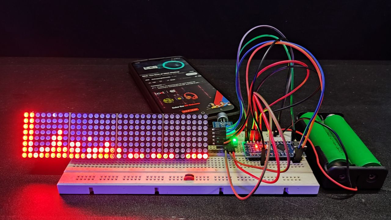
Audio Spectrum Visualizer Circuit Connection
The complete circuit connection for interfacing the 32×8 LED Dot Matrix Display and sound sensor with Arduino Nano is described below.
Both the Dot Matrix Display and sound sensor are using 5V power supply from the Arduino Nano 5V output pin. But you can use an external power source for better current supply. The Analog data pin of the sound sensor is connected to the A0 pin of the Arduino Nano.
Now, come to the Dot Matrix Display part. Connect the VCC and ground pin of the display module to the +5V and ground pin of the Arduino Nano respectively. Also, connect the DIN, CS, and CLK pins to the D11, D10, and D13 of the Arduino Nano.
Arduino Code
To compile this code, you have to have to install these two libraries into your Arduino IDE.
arduinoFFT.h
MD_MAX72xx.h
You can find these in Sketch > Include Library >Manage Libraries > click on the search bar type these and install.
#include <arduinoFFT.h>
#include <MD_MAX72xx.h>
#include <SPI.h>
MD_MAX72XX disp = MD_MAX72XX(MD_MAX72XX::FC16_HW, 10, 4);
arduinoFFT FFT = arduinoFFT();
double realComponent[64];
double imagComponent[64];
int spectralHeight[] = {0b00000000, 0b10000000, 0b11000000,
                        0b11100000, 0b11110000, 0b11111000,
                        0b11111100, 0b11111110, 0b11111111
                       };
int index, c, value;
void setup()
{
  disp.begin();
  Serial.begin(9600);
}
void loop()
{
  int sensitivity = map(analogRead(A6), 0, 1023, 50, 100);
  Serial.println (analogRead(A6));
  for (int i = 0; i < 64; i++)
  {
    realComponent[i] = analogRead(A0) / sensitivity;
    imagComponent[i] = 0;
  }
  FFT.Windowing(realComponent, 64, FFT_WIN_TYP_HAMMING, FFT_FORWARD);
  FFT.Compute(realComponent, imagComponent, 64, FFT_FORWARD);
  FFT.ComplexToMagnitude(realComponent, imagComponent, 64);
  for (int i = 0; i < 32; i++)
  {
    realComponent[i] = constrain(realComponent[i], 0, 80);
    realComponent[i] = map(realComponent[i], 0, 80, 0, 8);
    index = realComponent[i];
    value = spectralHeight[index];
    c = 31 - i;
    disp.setColumn(c, value);
  }
}


Hello,
I attempted to replicate the circuit you mentioned. After compiling, the RGB matrix operates for approximately one minute and then it stops.
Could you please help
Dear, guru your project is awesome,
i want to do this project but i decided to run the code,
it is showing fatal error: FFTWINDOW is not a class,
expansion of macro ‘FFT_WIN_TYP_HAMMING’
expansion of macro ‘FFT_FORWARD’ Error compiling.
Kindly help.
Thanks.
Yes, my sound sensor have microphone.
this is awesome, I was just posting about something like this, but I don’t need the whole spectrum, Just divided into 4, Low frequency, Med Low, Med High and High.
50 to 100 Hz, 100 to 300 Hz, 300 to 800 Hz and 800 to 1300 Hz.
Is your sound sensor a Microphone or do you have a direct input jack for line-level audio? Thank you.
Michel
Very well laid out plan, thank you for sharing! I am putting it on my project list.