In this project, I will build a 4558 IC-based bass booster circuit for low power audio amplifier. Audio without beats is impossible. To make an audio system with a bass feature ability, I introduced a bass booster circuit that gives a clear bass without any disturbance.
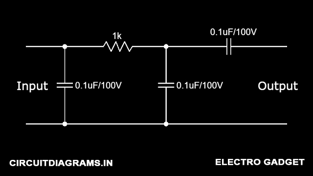
Bass sound is a very low-frequency sound that is generated by a low-pass filter circuit. It can block high frequency and produce low-frequency output. After going to build this circuit first we should know about the Low-Pass filter.
What is a Low Pass Filter?

A low-pass filter (LPF) circuit is a filter that passes signals with a frequency lower than a selected cut-off frequency and attenuates signals with frequencies higher than the cut-off frequency. The exact frequency response of the filter depends on the filter design. The filter is sometimes called a high-cut filter, or treble-cut filter in audio applications. A low-pass filter is the complement of a high-pass filter.
For more information just check Passive Low-Pass Filter
Note: If you want to plan to imply this 4558 ic circuit for bass and treble both, then this is not the right circuit. It only gives bass as its output.
Must Read LM386 Audio Amplifier
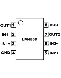
4558 IC Pinout

4558 IC Pin Configuration
| Pin | Name | Description |
|---|---|---|
| 1 | OUT1 | 1 no. output pin |
| 2 | IN1- | 1 no. inverting input pin |
| 3 | IN1+ | 1 no. non-inverting pin |
| 4 | GND | ground pin of op-amp |
| 5 | IN2+ | 2 no. non-inverting pin |
| 6 | IN2- | 2 no. inverting input pin |
| 7 | OUT2 | 2 no. output pin |
| 8 | VCC | Positive power supply |
Features and Characteristics of 4558 IC
- Two individually operated op-amps
- Low noise interference among op-amps
- Continuous Short-Circuit Protection
- No frequency Compensation Required
- No latch-up
- Large common mode and differential voltage range
- Gain and phase match between amplifiers
- Low noise input transistors
- Moisture Sensitivity Level 3
- Parameter tracking over a temperature range
- CMRR (Common-Mode Rejection Ratio): 80dB
- Single Supply Operation: +5.0 V to +15 V
- Dual Supply Operation: +15V and -15V
- Operating temperature: 0ºC to 70ºC
- Total power dissipation: 200mW
For more about 4558 IC check out LM4558 Dual Op-Amp
Circuit Diagram

Components Required
- 4558 IC
- 0.1uF/100V Capacitor
- 1uF/25V Capacitor
- 100KΩ Potentiometer
- 22KΩ Resistor
- 100KΩ Resistor
- 12-0-12V (1-3 Amp) Transformer
For implementing this circuit to a high-frequency audio amplifier, then a TDA2030 amplifier is the best DIY TDA2030 Audio Amplifier.
Yes using a voltage divider between pins 8, 5 and 4.
No, you need to give positive and negative 12-volt supply and ground to the op-amp for operation.
Can I power this circuit using 12v 1A single supply
Corrected it. There is no 470-ohm resistor that is mentioned in the required components. It’s our fault. Sorry for that
470 ohm resistor is missing from schematic.
Please tell what to do