Controlling temperature is very essential in many places such as smart houses, server rooms, and various types of industries where cooling is essential at all times. So this Arduino Temperature Controlled Fan can be very useful for understanding the basic principle, of how can we operate and maintain the temperature at our home. We can use this project anywhere as a portable device where the fan changes speed with the temperature change.
In this project, I am going with a very common DHT11 temperature and humidity sensor for better results. This project can also be done in other simple ways as well using a thermistor or other temperature sensors like LM35, DS18B20 etc. But thermistor needs physical contact with hot surfaces which is not accurate in some cases and contactless sensors are costly. While DHT11 is a cost-effective sensor and also a minimal contactless sensor.
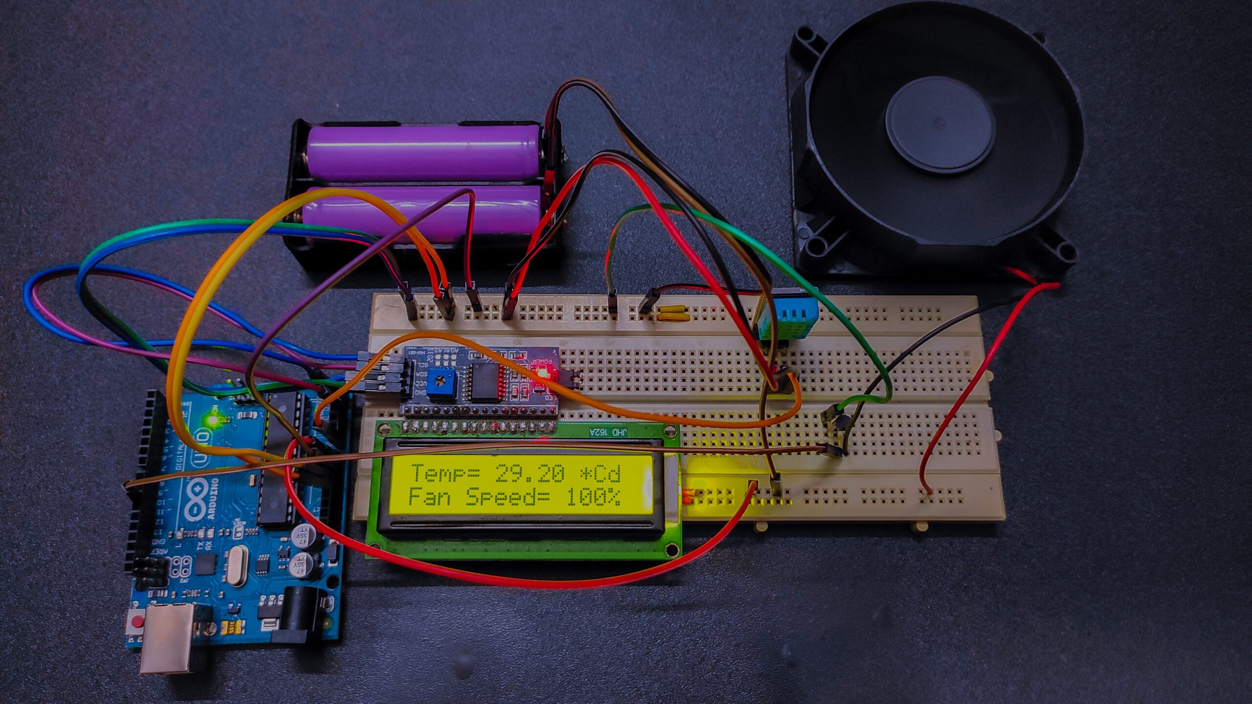
With this device, we can be able to change the fan speed in our home or any place according to the room temperature. It also displays the real-time temperature and the changes in fan speed on a 16×2 LCD. We are using here an Arduino, a 16×2 LCD, a DHT11 sensor module, and a DC fan.
Must Read Temperature Controlled DC Fan Without Any Microcontroller
Project

Circuit Diagram

Components Required
- Arduino
- DHT11 Temperature & Humidity Sensor
- 16×2 LCD Display
- 2N2222 Transistor
- 1KΩ Resistor
- 12 Volt DC Fan
- Breadboard
- 12 Volt Power Supply
- Wires
Working Principle of Arduino Temperature Controlled Fan
This project has three different parts. In the first part, the DHT11 sensor senses the surrounding temperature. In the second part, the microcontroller reads the input data from the DHT11 sensor converts that data to a suitable Celsius value and drives the speed of the DC fan using a PWM signal. The third one includes the display part where the 16×2 LCD shows the real-time temperature and the speed of the DC fan.
A detailed demo of the DHT11 temperature and humidity measuring system where you will find the working principle of the DHT11 sensor.
The Analog value is then applied to the Analog to Digital converter pin of the Arduino. After that, the Analog value will be converted into a digital value using successive approximation methods. When the temperature value crosses the threshold value, Arduino sends a command signal to the motor driver using PWM output to switch on the DC fan.
We have created a PWM signal at the PWM pin of the Arduino board and applied it at the base terminal of the 2N2222 NPN transistor. Then transistor creates a voltage according to the PWM input given.
What is a PWM Signal?
Pulse Width Modulation (PWM) or Pulse Duration Modulation (PDM) is a technique for reducing the average power delivered by an electrical signal. The average value of voltage or current fed to the load is controlled by turning the switch between supply and load on and off at a fast rate. It is a square wave that operates as a switch constantly on and off. It is widely used to control the speed of a DC motor and dimmable light bulb.
Working Value of DC Fan According to Temperature Value
| Temp | PWM Value | Speed |
|---|---|---|
| <26 | 0 | 0 |
| 26 | 51 | 20% |
| 27 | 102 | 40% |
| 28 | 153 | 60% |
| 29 | 204 | 80% |
| >29 | 255 | 100% |
Applications of Arduino Temperature Controlled Fan
- This device is useful for home automation systems where temperature maintenance is essential with automated technic.
- Can be used in a CPU cooling system to reduce extra energy consumption.
Arduino Code
#include "DHT.h"   //Library for DHT11 sensor
#include<LiquidCrystal.h>   //Library for 16x2 LCD display
LiquidCrystal lcd(7, 6, 5, 4, 3, 2);   //Define 16x2 LCD display pins
#define DHTPIN A0     //Define analog pin A0 as DHT11 sensor pin
#define DHTTYPE DHT11
#define pwm 10    //Define digital pin 10 as PWM output
//You can use either D9 or D10 as a PWM output
byte degree[8] =
              {
                0b00011,
                0b00011,
                0b00000,
                0b00000,
                0b00000,
                0b00000,
                0b00000,
                0b00000
              };

//Initialize DHT sensor for normal 16MHz Arduino
DHT dht(DHTPIN, DHTTYPE);
void setup()
{
 lcd.begin(16, 2);
 lcd.createChar(1, degree);
 lcd.clear();
 lcd.print("Temperature Controlled");
 lcd.setCursor(0,1);
 lcd.print("  DC Fan ");
 delay(2000);
 analogWrite(pwm, 255);
 Serial.begin(9600);
 dht.begin();
}
void loop()
{
  delay(2000);
  float t = dht.readTemperature();

  if (isnan(t))
  {
    Serial.println("Failed to Read From DHT Sensor");
    return;
  }
  lcd.setCursor(0,0);
  lcd.print("Temp= ");
  lcd.print(t);     //Showing temperature on LCD display
  lcd.print(" *C");
  lcd.setCursor(0,1);

   if(t<20)
    {
      analogWrite(9,0);
      lcd.print("Fan Speed= 0%    ");
      delay(1000);
    }

    else if(t==26)
    {
      analogWrite(pwm, 51);
      lcd.print("Fan Speed= 20%   ");
      delay(1000);
    }

     else if(t==27)
    {
      analogWrite(pwm, 102);
      lcd.print("Fan Speed= 40%   ");
      delay(1000);
    }

     else if(t==28)
    {
      analogWrite(pwm, 153);
      lcd.print("Fan Speed= 60%   ");
      delay(1000);
    }

    else if(t==29)
    {
      analogWrite(pwm, 204);

      lcd.print("Fan Speed= 80%    ");
      delay(1000);
    }
     else if(t>29)
    {
      analogWrite(pwm, 255);
      lcd.print("Fan Speed= 100%   ");
      delay(1000);
    }
  delay(3000);
}


Thank you for that clarification. It was my mistake
Hi,
I think there is a mistake in line 65.
I think it should have been “else if(t==27)” and not “else if(t==20)”.
Best regards,
Avi Salto