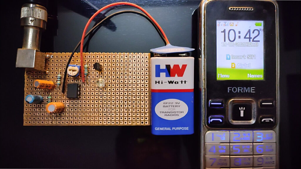
In this tutorial, I will show you a simple mobile phone detector project using a cheap LM358 op-amp. This mobile phone detector can detect the nearness of an active cell phone from a separate distance of four to five meters. So it can come helpful in an assessment lobby or gatherings where cell phones are not allowed.
The mobile phone detector circuit can recognize approaching and active calls, SMS, internet, and video transmissions regardless of whether a mobile phone is kept in quiet mode. At the point when it recognizes an RF signal from an initiated mobile phone, its LED begins flickering and keeps on flickering until the signal stops.
Project

Circuit Diagram

Components Required
- LM358 Op-Amp
- BC548 NPN Transistor
- 100uF/16V Electrolytic Capacitor
- 1uF/16V Electrolytic Capacitor
- Resistors (1KΩ, 220KΩ, 100KΩ)
- 100K Preset
- LED
- Antenna
- Connecting Wires
- 3.7V Battery
Circuit Connection for Mobile Phone Detector Circuit
In this mobile phone detector, at first, pin 8 and pin 4 of the LM358 op-amp are directly connected to the Vcc and ground respectively.
Pin 3 is connected to the ground through a 100uF electrolyte capacitor and to the VCC through a 220KΩ resistor. Pin 3 is also connected with pin 2 through a 1uF electrolytic capacitor.
A 100KΩ preset is taken and its right terminal is connected to pin 1 and the left terminal is connected to pin 2 and the middle terminal is connected to pin 1 of the op-amp IC.
An NPN transistor of its base terminal is connected with pin 1 of the IC. Another collector and emitter terminal are connected with Vcc through a 1KΩ resistor and cathode of the LED respectively. The anode terminal of the LED is directly connected to the ground.
Pin 2 is connected through two capacitors parallelly and also with a 100KΩ resistor to the ground. An antenna is connected also from pin 2 of the IC.
A 5V power supply is attached to the circuit to distribute the required power.
Working Principle of Mobile Phone Detector Circuit
At the point when a mobile phone is activated, it radiates an RF signal that goes through close by space. The signal contains electromagnetic RF radiation from the cell phone.
Capacitor C1 is utilized in the circuit to distinguish the RF signal from the cell phone. At the point when the cell phone radiates an RF signal, C1 retains it and gives it to the contributions of IC. This is shown by the flickering of the LED. Potentiometer VR1 is utilized to change the scope of the circuit. Transistor T1 is utilized to intensify the signal got at pin 1 of the IC.
This mobile phone detector circuit is appropriate for 2G systems, GPRS, and network searches. It doesn’t identify 3G, WCDMA, and HSDPA networks so well.
Application of Mobile Phone Detector Circuit
- This mobile phone detector can detect the nearness of an active cell phone from a separate distance of four to five meters.
- It can come helpful in an assessment lobby or gatherings where cell phones are not allowed.
Very interested, I did it as my final year project and it works well
Proteus, EasyEDA.
IN WHICH SOFTWARE I CAN PERFORM SIMULATION.
Nice project