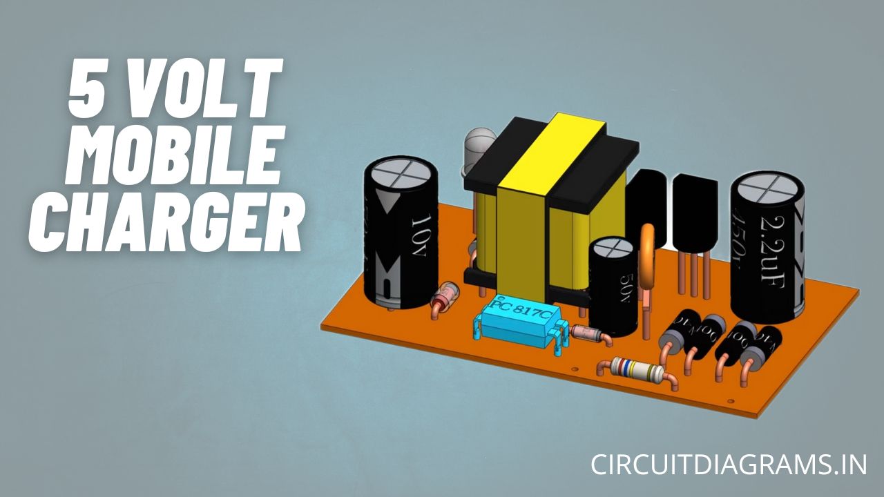
We use our smartphones every day. But have you ever wondered how your smartphone mobile charger actually works? You would know that a charger converts AC into DC, but it is not that straightforward. First, it converts AC to DC then again back to AC and finally to DC. Today we are going to see how the 5V mobile charger circuit does this and why are their intermediate steps.
Must Read LM317 Variable Power Supply
Project

This is a normal charger circuit that converts 220V AC to 5V DC. Let’s see what’s inside. Now we can see all the electronic components used in it. There are diodes, capacitors, transistors, resistors, transformers and an optocoupler. Also, there are resistors below the PCB. Once the power is on, it turns on. To understand it better, let’s rearrange the circuit.
Circuit Diagram of Mobile Charger Circuit

Components Required
- Ferrite Transformer
- PC817C Optocoupler
- 1N4007 PN Bridge Rectifier Diode (x4)
- 1N5819 Schottky Diode
- Resistor (2MΩ, 560Ω, 1KΩ, 10Ω, 120Ω, 100Ω)
- 2.6Ω/1W Fuse Resistor
- S8050 NPN Transistor
- 13001 NPN Transistor
- 2.2uF/450V Polyester Film Capacitor
- 4.7nF/100V Polyester Film Capacitor
- 470uF/25V Electrolyte Capacitor
- 22uF/25V Electrolyte Capacitor
- 100nF Ceramic Capacitor
- 4.2V Zener Diode
- Red LED
- Veroboard
Circuit Connection of Mobile Charger Circuit
Now we can see all the components and connections. The red wire is phase wire and the black is neutral. First, we have a resistor. By observing the colour bands and reference table, we can see it is 2.6Ω. This is a fusible resistor that prevents damage from overloading. Then there is a bridge rectifier made of four 1N4007 PN junction diodes and a filter capacitor of 2.2uF/450V.

This is an oscillator circuit. This converts DC back to high-frequency AC of 15 to 50 KHz. We can see the values of the components. These are two NPN transistors S8050 and 13001, and these are their pin configurations below.


After that portion, there is a small diode. It looks like a Zener diode, but it’s a fast switching diode i.e. 1N4148 and has a capacitor value of 22uF/63V.

This is an AC-to-DC converter for the phototransistor in the optocoupler, It forms a circuit like this. For the transmission of signals without contact, we use it. On the right side, we have an infrared led and on the left is a phototransistor. When the LED turns on its light turns on the base of the phototransistor turning it on. This capacitor is of 100nF used for safety purposes. It is connected between primary and secondary grounds to stop electromagnetic interference.

This is the transformer, it has three windings; primary, secondary, and auxiliary winding wrapped around the core. It is used here to step down the voltage. The auxiliary winding is used to run the oscillator circuit.
Then we have a Schottky diode 1N5819 with a capacitor of 470uF/16V to convert AC to DC and a LED for indication. Also, there is a feedback circuit that consists of an optocoupler PC817C and a 4.2V Zener diode.
Working Principle of Mobile Charger Circuit
Let’s turn it on and see it in action. The red wires carry the positive voltage and the black wires carry the negative voltage or ground.

We have the input of 220V 50Hz AC. This is a bridge rectifier, it converts AC to fluctuating DC. As we can see this fluctuating DC filters from the capacitor and becomes almost pure DC. We can see we have DC in the circuit. Now, this current passes from the 2M ohm resistor to the base of the Q1 transistor to turn it on. This transistor isn’t fully turned on, because of the resistance it turns on partially. Due to the partial turning on of the transistor, a low current passed from the primary winding of the transformer. This induces a low voltage in the auxiliary winding.
The induced voltage now charges the capacitor and then the capacitor fully turns on the transistor. As the transistor is now fully on, it allows the current to flow through itself. Now, this turns on the transistor Q2, this shunts the base of the Q1 transistor turning it off. As the Q1 turns off the flow of current to the Q2 is cut off. Now the current flows to the base of the Q1 and the cycle repeats.
This situation happens at 15 to 50 kHz which is a thousand times faster than the rectifier circuit. Hence, you would see that the rectifier circuit is stopped. At the same time, the voltage from the auxiliary also turns the diode on and charges the capacitor and flows to the optocoupler. This diode and capacitor convert the AC signal from the auxiliary coil to the DC for the optocoupler.
The current is also induced in the secondary winding. This is converted to DC by a Schottky diode and a filter capacitor. It is indicated by the LED. But what if the voltage is more than 5 volts? Hence, we have a feedback circuit. As we reach 4.2V the Zener diode turns on allowing the current to flow to the optocoupler. It also drops the voltage by 4.2V, hence the Transmitter LED of the optocoupler doesn’t turn on. The Transmitter LED requires 0.8V to turn on. When the voltage reaches more than 5V, this turns on the LED of the optocoupler.
The infrared light of the Transmitter LED turns on the phototransistor of the optocoupler allowing the current to flow to the transistor T2. This turns on the transistor T2 shunting the first and stopping the flow of current in the primary winding. Also, the voltage in the secondary side of the transformer drops below 5V, turning off the Zener diode and optocoupler. The circuit is continuous to run normally.
Why We Should Not Directly Convert AC to DC Than This?
This is because of the normal power supply which is at 50 or 60 hertz. The size of the transformer and the capacitors are large. They cannot be mounted in a small charger like this. Hence in the 5V mobile charger, the 50 or 60-hertz frequency is converted to 50 kilohertz. This reduces the size of the transformer and capacitor required in the circuit. So to change the frequency of AC first we have to convert it to DC and then again back to AC.
Now you know how the 5V mobile charger circuit that we use daily works.


hello sir
sir whare is sunbber circuit?
Great explanation! I never understood the inner workings of mobile chargers before. The diagrams really helped clarify how the components interact. Thanks for sharing this insightful post!
Perhaps Q1 and Q2 is confusing. 13001 should be term as Q1. Q1 is starts at most initial stage. Then Q2 S8050 gets shorted when coacitor 22 uf charges through 1 k resistor. This makes off the transistor 13001. Due off of S8050 Q2 produce voltage in auxiliary winding at point 3 and 4 and again it chargesthe capacitor 22 uf and turns on S8050 making short collector and emitor of S8050. Which again makes transistor 13001 off. This process is repeating.
This post is incredibly informative! I never realized how complex mobile charger circuits are. The breakdown of each component and its function really helped me understand the entire process. Thanks for sharing such clear insights!
Great explanation of mobile charger circuits! I loved how you broke down the components and their functions. It really helped me understand how the charging process works. Thank you for sharing this insightful post!