What is An Inverter?
Inverters have taken a prominent role in the modern technological world due to the sudden rise of electric cars and renewable energy technologies. Inverters convert DC power to AC power as they are also used in uninterruptible power supplies to control electrical machines and active power filtering.
This article will explain how to get a pure sinusoidal electric power output from DC power input in a step-by-step logical manner.
An alternating current periodically reverses its direction. For this reason, the average value of alternating current over a cycle will be zero.
Before proceeding to sine-wave production Let’s see how a square-wave alternating current is produced. In fact, the old type inverters used to produce simple square waves as their output.
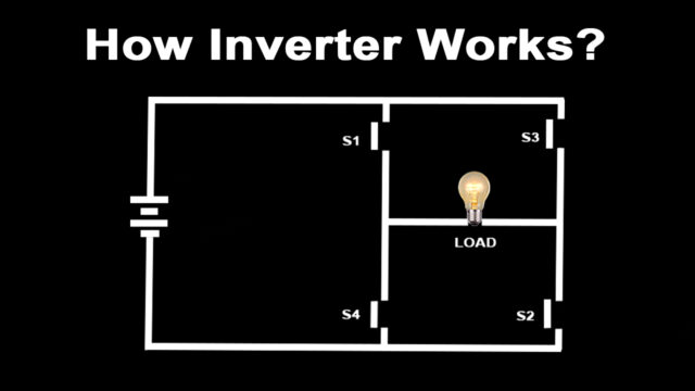
Let’s build an interesting circuit as shown with four switches and one input voltage

This circuit is known as a full-bridge inverter the output is drawn between points A and B. To make this circuit analysis easier, let’s replace this actual load with a hypothetical load. Just note the current flow when S1 and S2 are on and S3 and S4 are off.
Now just do the reverse and observe the current flow. It is clear that the current flow is the opposite in this case, as is the output voltage across the load. This is the basic technique that produces a square wave alternating current.
We all know that the frequency of the AC supply available in our homes is 60/50 Hertz. This means that we need to turn the switch on and off 120 times in a second, which is not possible whether manually or by using mechanical switches.

We introduce semiconductor switches such as MOSFET for this purpose. They can turn on and turn off thousands of times per second. With the help of control signals, we can turn transistors on/off very easily.
The square wave output is a high approximation of sine wave output. Old inverters are used to produce them. That’s why you hear a humming noise when you run your electric fan or other appliances using square wave power. They also heat up electric equipment.
Modern inverters produce pure sinusoidal output.
let’s see how they achieve it.

A Technique called Pulse Width Modulation is used for this purpose. The logic of pulse width modulation is simple. Generate the DC voltage in the form of pulses of different widths. In regions where you need higher amplitudes, it will generate pulses of larger, width. The pulses for the sine wave look like the above diagram.
Now here is the tricky part.
What Will Happen If You Average These Pulses in a Small Time Interval in Inverter?

You will be surprised to see that the shape of the averaged pulses looks very similar to the sine curve. The finer the pulse is used the better shape the sine curve will be.
How to Make These Pulses and How Do We Average Them in a Practical Way?

Let’s see how they are implemented in an actual inverter.
Two comparators are used for this purpose. Comparators compare a sine wave with triangular waves. One comparator uses a normal sine wave and the other comparator uses an inverted sine wave. The first comparator controls MOSFET1 and MOSFET4 and the second comparator controls MOSFET3 and MOSFET2. MOSFET1 and MOSFET4 determine the voltage level at Point “A” and the other two MOSFETs determine the voltage level at Point “B”.
You can see that the one branch of comparator output is fitted with a logic not gate. This will make sure that when MOSFET1 is on and MOSFET4 will be off and vice versa. This also means that we can never turn on MOSFET1 and MOSFET4 at the same time. Which will cause the DC circuit to short-circuit.
Turning MOSFET1 gives cell voltage at Point “A” and turning on MOSFET4 gives zero voltage at the same point.
The same is the case for point “B”.
The switching logic of PWM is simple. When the sine wave value is more than the triangular wave, the comparator produces one signal, otherwise a zero signal.
Now observe voltage variation at the first comparator according to this logic. The control signal of one turns on the MOSFET.
The voltage pulses produced at Point A are shown

Apply the same switching logic and observe the voltage pulses generated at point “B“.
Since we are drawing output voltage between points “A“ and “B“, the net voltage will be the difference between “A” and “B”. This is the exact pulse train we need to create this sine wave. The finer the triangular wave the more accurate the pulse train will be.
How Do We Practically Implement the Averaging?
To make it exactly sinusoidal energy storage elements such as inductors and capacitors are used to smooth the power flow. They are called passive filters. Inductors are used to smoothen the current and capacitors are used to smoothen the voltage.
With an inverter bridge a good PWM technique and a passive filter, you can generate sinusoidal voltage and operate all of your appliances without any fuse.
The inverter technology we have explained so far has only two levels of voltage. What if we introduce one more voltage level? This will give a better approximation of the sine wave and can reduce instantaneous error. Such multi-level inverter technology is used in high-precision applications like wind turbines and electric cars.
The inverter used in electric cars has intelligent frequency and amplitude control. In fact, frequency controls the speed of an electric car and amplitude controls the power of it. This way inverters act as the brain of electric cars by producing electric power ideal for driving conditions.
We hope this article provided you with a good introduction to the workings of inverters.


Switch over time is a master while electricity cut and you have explained in a meaningful way in your diagrams. Keep posting.