A stun gun is a device used to generate a high voltage and low current signal. It is mostly used as a weapon to stun or shock waves to the target. The shock of it gets weak or paralyses the target. For its application, some countries banned this stun gun. This is actually a weapon that can paralyze a person mentally.
In this project, we are going to build this stun gun using a 555 Timer to generate a current fluctuating signal and a voltage multiplier using a transformer and a multiple-stage arrangement of voltage doubler with capacitors and diodes. this circuit can operate using a 9V battery power supply.
Must Read 555 Timer Mini Project
CAUTION: In some countries, it is strictly prohibited as it is a type of weapon. I made this project for educational purposes only.
Also, it contains high DC voltage on the output side. So do not try to implement this circuit practically.
Principle Behind This Stun Gun
The basic principle behind this project is a conventional stun gun. An oscillating signal frequency is created by the 555 Timer by the external elements connected with it. The step-up transformer which produces a high-voltage signal is fed low-current electric pulses. It can be increased by the voltage multiplier circuit. The voltage multiplier circuit is made by voltage doublers. The voltage doublers are consisting of two diodes and two capacitors. The Villard Doubler Method is used in this stage. So the output voltage is proportional to the number of doublers used in the circuit.
Project

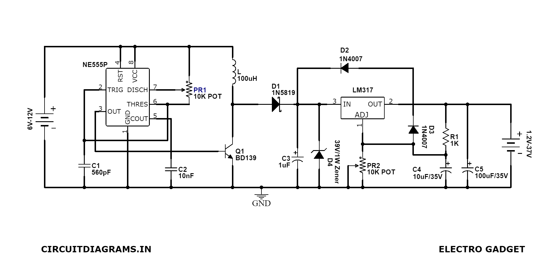
Circuit Diagram

Components Required
- Flyback Transformer
- IRF220 Transister
- LM555 Timer IC
- 10KΩ Potentiometer
- 0.1uF Ceramic Capacitor (C1)
- 10uF/2500V Capacitor (x11) (C2-C12)
- 1N4007 PN Diode (x10)
- 750Ω Resistor
- Push Switch
- 9V Battery
Circuit Connection
There are two parts to the circuit design. The astable multivibrator and the voltage multiplier. The requirement of this project is to generate 10KV DC voltage from 1000V input.
Now the formula is,
Vout = (2Vin + 1.414) × S
S = number of stages
To get 10KV, 5 stages of voltage doubler are required.
After the calculation, we know that we are going to design a 5-stage voltage multiplier circuit. The output of this circuit generates 10KV DC with an input of 1000V. So the capacitors must have a voltage rating of at least 1000V. We need a 10uF/2500V capacitor for this because the operating frequency is low here.
Now we started to design the astable multivibrator circuit. To design an astable multivibrator with 555 Timer IC, we need some passive external components. We assume the required frequency is about 50 HZ. For a duty cycle of 75%, we calculate R1 = 1.44KΩ, R2 = 720Ω and C1 = 10uF/2500V. So we select a 2KΩ potentiometer, 720Ω resistor and 10uF/2500V capacitor respectively. We know very low frequency is used here, so we use IRF530 MOSFET for this operation.
Working Principle of Stun Gun Circuit
After pressing switch S1, the astable operation of 555 Timer starts. The pulsating electric signal of a low current is generated. The step-up transformer stepped up this signal to a voltage of 1000V. The signal which is given from the Timer is through a MOSFET switch.
In the phase of the positive half cycle, capacitor C3 is charged through the diode D1. When D1 is forward-biased. So the capacitor has no path to discharge. Hence it stores the charge. This generates a voltage that is equal to the AC input peak value at its end.
In the phase of the negative half cycle, diode D2 is forward-biased. So capacitor C4 charged through the D2 and C3. At the end of this cycle, the voltage is equal to double the input AC voltage.
In the next positive half cycle, diode D3 is forward-biased. Capacitor C5 takes charge in this position. Then the next half-cycle, D4 is forward biased and C6 charged. At the end of this, the voltage is equal to 4 times the input peak voltage. It is obtained at point 2. The process repeats for another two states. At last a voltage equal to 10 times the input voltage. It is obtained at point 5.
Stun Gun Circuit Limitations
- This circuit involves high pulse production, so this circuit is very risky to use. The implementation of this is needed very carefully to handle it.
- Anyone does not touch the output of this circuit. This may cause death or paralyze body parts.
This circuit can not be used in the presence of persons with cardiac issues. - The transformer used in this project is quite complex and costly.
Applications of Stun Gun Circuit
- This project can be used for security purposes.
- It can also be used as protection from wild animals.
- As modern war equipment.


You have a unique ability to turn abstract ideas into something tangible and actionable. That’s incredibly helpful for your readers.
I want to make a similar project for school but, I dont know what type of flyback transformer are you using here.