We have already discussed some ESP8266 NodeMCU based projects in previous. Now we are going to build a so-called popular WiFi Smart Plug using the Blynk application. In Home Automation System in our daily life, we all love to control our devices using just one device or main controller. WiFi Smart Plug is one such device that helps us to do that very easily. It allows you to control almost every wired device like table fan, lights, AC, etc. In my case, I have long wanted to make such WiFi Smart Plug that would be able to switch my AC on/off.
Many of that WiFi Smart Plugs are available on today’s market, but these smart plugs are pretty expensive to buy. So making your own WiFi Smart Plug like “Sonoff” is more interesting and quite easy. Also, it is easy to control, just plug it into any existing socket and on the other hand plug any electronic device into the smart plug. Then just keep the main switch of the existing socket always on and control devices from your smartphone directly.
What is WiFi Smart Plug?
A WiFi Smart Plug is like a power-point adapter. It fits between your power socket and the appliance you wish to plug in. Most of the smart plugs communicate (any Wi-Fi network) to a central control hub. Then, the hub uses your Wi-Fi to send information to an app on your smartphone.
Principle Behind the WiFi Smart Plug
The principle behind this WiFi Smart Plug is to turn on and off of devices from your smartphone or any other controlling device. It’s very simple, just plug it into a socket and turn the power on. Now plug any devices or lamp into the WiFi socket. That’s it. Now the AC power from the main socket gives the power to the WiFi Smart Plug. By the user’s command from the android app, it turns on and off the following devices.
Project

Circuit Diagram

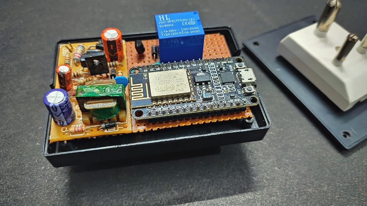
Components Required
- ESP8266 WiFi Module (ESP-01/NodeMCU)
- 5V Relay Module
- 5V AC to DC Hi-Link Converter
- 3 Pin Multiplug for Enclosure
- Any WiFi Router/Mobile Hotspot Connection
- Vero board
- Wire
- AC Source
Pin Description Used in This Circuit
- VCC: Power supply pin of ESP8266 which can be supplied with 3.3V DC.
- GND: Ground reference pin of ESP8266 for ground supply to the circuit.
- RST: It is used to reset the module and it is an active LOW pin.
- GPIO16: For enabling reset pin.
- GPIO5: For output of relay module.
How to Program NodeMCU Using Arduino IDE?
To use the Arduino IDE software to program the NodeMCU, we need to first install the appropriate board into the IDE software. For this copy the following link (http://arduino.esp8266.com/stable/package_esp8266com_index.json) and paste it into the blank box as shown in the picture.

First, click Preferences in the File menu and enter the copied link in the Additional Board Manager URLs part. Then press OK.

Next, find the ESP8266 option in Boards>boards manager from the Tools menu. Then install the ESP8266 board. After successful installation, we can compile code in IDE software.

Blynk Application Setup for WiFi Smart Plug
We are going to use the Blynk app as our IoT server to enable devices to communicate with the cloud server. Install new Blynk IoT application from smartphone and login or sign up to the app. After open click on the Settings icon from the upper right corner and click Add Template and name it.
Then open this and click again on another type of settings icon from the upper right corner. We can see the template id and we need to copy it for coding purposes. From there choose desired Data Stream button and select the mode for the Switch option. That’s it.

Now back once and click on the triple bar icon from the right upper corner. From there choose the Button icon. Then click on this button icon and set the Data Stream value to zero and mode to Switch.
After that, back to the home screen and click on Add New Device. After the WiFi scan, the available devices will be shown there. Then select the device and control it through this app.
Benefits of WiFi Smart Plug
- A smart plug can turn any of your existing appliances and electrical devices into smart objects that can communicate with other smart products in your home.
- Using the smartphone app, you can turn appliances on and off remotely anywhere in the world and even check to see if you left an appliance running after you’ve left your home.
- You can also monitor how much energy an appliance used directly from your smartphone. Smart plugs will even notify you if a device suddenly starts using unusual amounts of energy.
- Burglars often target homes which is empty. WiFi Smart Plugs can be used to improve home security by turning lights and appliances on and off while you’re on vacation. Burglar will think you are home while you are far from home.
- Using a smart plug, you can control your devices also with voice commands like Google Assistant, Alexa, Siri, etc.
NodeMCU Code
For compiling code, we first need some library files that are all included in this link Blynk Library Files. Just download it and paste it all with the main NodeMCU code. That’s it.
#define BLYNK_TEMPLATE_ID "TMPLC9GS7yP8"
#define BLYNK_DEVICE_NAME "WiFi Smart Plug"

#define BLYNK_FIRMWARE_VERSION    "0.1.0"
#define BLYNK_PRINT Serial

#define APP_DEBUG
#define USE_NODE_MCU_BOARD

#include "BlynkEdgent.h"

#define RELAY_PIN_1               5 // D1
#define RELAY_PIN_2               4 // D2
#define PUSH_BUTTON_PIN_1         14 // D5
#define PUSH_BUTTON_PIN_2         12 // D6

#define VIRTUAL_RELAY_1                           V0
#define VIRTUAL_RELAY_2                           V1

#define BUTTON_NUM                                 2
#define BUTTON_NO_PRESS                           -1
#define BUTTON_PLUG_1                              0
#define BUTTON_PLUG_2                              1

#define ON                                         1
#define OFF                                        0

short gsArray_Button[BUTTON_NUM] = {PUSH_BUTTON_PIN_1, PUSH_BUTTON_PIN_2};
unsigned short gusIsRelay_1_On = OFF;
unsigned short gusIsRelay_2_On = OFF;
unsigned short gusIsBut_Pressed = 0;

void setup()
{
  Serial.begin(115200);
  delay(100);

  BlynkEdgent.begin();

  pinMode(RELAY_PIN_1, OUTPUT);
  pinMode(RELAY_PIN_2, OUTPUT);
  pinMode(PUSH_BUTTON_PIN_1, INPUT_PULLUP);
  pinMode(PUSH_BUTTON_PIN_2, INPUT_PULLUP);

  vRelay_Control(BUTTON_PLUG_1, OFF);
  vRelay_Control(BUTTON_PLUG_2, OFF);
  vBlynk_Write_Button_State(BUTTON_PLUG_1, OFF);
  vBlynk_Write_Button_State(BUTTON_PLUG_2, OFF);
}

void loop()
{
  short sBut = BUTTON_NO_PRESS;

  BlynkEdgent.run();
  sBut = sRead_Button();

  if(sBut == BUTTON_PLUG_1)
  {
    if(gusIsBut_Pressed == 0)
    {
      if(gusIsRelay_1_On == ON)
      {
        vRelay_Control(sBut, OFF);
        vBlynk_Write_Button_State(sBut, OFF);
      }
      else
      {
        vRelay_Control(sBut, ON);
        vBlynk_Write_Button_State(sBut, ON);
      }
      gusIsBut_Pressed = 1;
    }
  }
  else if(sBut == BUTTON_PLUG_2)
  {
    if(gusIsBut_Pressed == 0)
    {
      if(gusIsRelay_2_On == ON)
      {
        vRelay_Control(sBut, OFF);
        vBlynk_Write_Button_State(sBut, OFF);
      }
      else
      {
        vRelay_Control(sBut, ON);
        vBlynk_Write_Button_State(sBut, ON);
      }
      gusIsBut_Pressed = 1;
    }
  }
  else
  {
    gusIsBut_Pressed = 0;
  }
}
short sRead_Button(void)
{
  short sStatus = BUTTON_NO_PRESS;

  for(short i = 0; i < BUTTON_NUM; i++)
  {
    if(digitalRead(gsArray_Button[i]) == 1)
    {
      delay(50);
      if(digitalRead(gsArray_Button[i]) == 1)
      {
        sStatus = i;
      }
    }
  }

  return sStatus;
}
BLYNK_WRITE(VIRTUAL_RELAY_1)
{
  short sVirtual_Status = 0;

  sVirtual_Status = param.asInt();

  vRelay_Control(BUTTON_PLUG_1,sVirtual_Status);
}
BLYNK_WRITE(VIRTUAL_RELAY_2)
{
  short sVirtual_Status = 0;

  sVirtual_Status = param.asInt();

  vRelay_Control(BUTTON_PLUG_2,sVirtual_Status);
}
void vRelay_Control(short sBut, short sOnOff)
{
  if(sOnOff == ON)
  {
    if(sBut == BUTTON_PLUG_1)
    {
      digitalWrite(RELAY_PIN_1, LOW);
      gusIsRelay_1_On = ON;
    }
    else if(sBut == BUTTON_PLUG_2)
    {
      digitalWrite(RELAY_PIN_2, LOW);
      gusIsRelay_2_On = ON;
    }
  }
  else
  {
    if(sBut == BUTTON_PLUG_1)
    {
      digitalWrite(RELAY_PIN_1, HIGH);
      gusIsRelay_1_On = OFF;
    }
    else if(sBut == BUTTON_PLUG_2)
    {
      digitalWrite(RELAY_PIN_2, HIGH);
      gusIsRelay_2_On = OFF;
    }
  }
}
void vBlynk_Write_Button_State(short sBut, short sStatus)
{
  if(sBut == BUTTON_PLUG_1)
  {
    Blynk.virtualWrite(VIRTUAL_RELAY_1, sStatus);
  }
  else
  {
    Blynk.virtualWrite(VIRTUAL_RELAY_2, sStatus);
  }
}


Very good article
Can I see more details like the setup of the Blynk app and how to monitor the energy consumption?
What type of details?
Pls send details