A Digital Watch is a great innovation in electronics science. Nowadays, digital watches are catching their attention everywhere. The Analog watches are quite old-fashioned. So the digital watch takes its place day by day.
In this tutorial, I will show how to use an ATtiny85 chip to build a tiny digital watch that can run over a long period of time without replacing the battery. And this is easy to available and cheapest microcontroller chip which is a replacement for all Arduino microcontrollers. Also, it is a compact one.
In a previous article, we also built a Digital Clock using RTC module. Also, read out this article.
Project

Circuit Diagram

Components Required
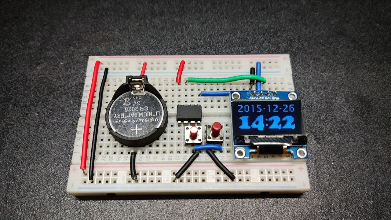
- ATtiny85
- OLED Display
- 2x Push Button
- Connection Wire
- 3V Lithium Ion Battery
About Parts of Digital Watch Using ATtiny85
ATtiny85 Microcontroller
The ATtiny85 microcontroller is powerful as well as the cheapest microcontroller IC available in the market. This microcontroller operates with an 8-bit data bus, which has the ability to access 8-bits of data per instruction. It has an 8MHz processing speed and 8KB of flash memory for storing programs. It contains 5 Input/Output pins (I/O pins) for connection. The operating voltage varies between 1.8V to 5.5V.
Pinout
- Pins 2, 3, 5, 6, and 7 are all capable of digitalWrite()/digitalRead() functions.
- Pins 5 and 6 are capable of PWM analogWrite() at 8-bit resolution (0-255).
- Pins A1, A2, and A3 are capable of analogRead(), measuring Analog voltage through a 10-bit Analog Digital Converter (ADC).
- Pin 1 is the RESET pin for restarting the program by connecting it to the ground.
- Pin 8 is used for giving positive voltage (1.8V – 5.5V) to the microcontroller.
- Pin 4 is for ground.
OLED Display
As we know, we have limited I/O pins available in our tiny Attiny85 chip, so I chose an I2C OLED display. It will fill our needs as it has only four pins that are VCC, GND, SDA, and SCL. Also, it is effective to reduce power consumption. Different types of I2C OLED displays are available in the market, but I chose the SSD1306 (128×64) display as it is small in size, and also in square form.
How to Upload Code to ATtiny85 Chip?
By default the Arduino IDE does not support the ATtiny85 board manager, so we need to add it manually.
Install ATtiny85 Board Manager
- First Go to File > Preferences then scroll down to Additional Board Managers URLs > copy and paste the following URL
https://raw.githubusercontent.com/damellis/attiny/ide-1.6.x-boards-manager/package_damellis_attiny_index.json
- After that, go to Tools > Board >Boards Manager
- A new tab will open and at the top of the tab type “ATtiny”
- Select Install on the Attiny by David. A Mellis
- Restart the Arduino IDE
Upload Code to ATtiny85
We can’t upload the code directly into the ATtiny85 chip. For that, we need an Arduino board as an ISP.
First, we need to create the Arduino Nano as a Master ISP.
- Go to Files > Examples > select ArduinoISP > open ArduinoISP code
- Then select Tools menu > board type Arduino Nano
- Select Processor to Atmega328 (Old Bootloader)
- Select Port
- Press the Upload button
Connect the Arduino Nano and Attiny85 as in the following circuit diagram.

- Go to Tools > Board > select ATtiny25/45/85
- Under Tools > Clock > 8 MHz (Internal)
- Under Tools > Processor > ATtiny85
- Under Tools >Programmer >Arduino as ISP
- Check that all wiring, capacitor, and board selections are correct
- Finally, select Burn Bootloader

Working Principle of Digital Watch Using Attiny85
Required Battery By Current Calculation
When we switch on the circuit, the microcontroller and OLED display consume about 6mA current.
In order to reduce the current and let the watch run for over one year, we need to use the power-saving sleeping mode, SLEEP_MODE_PWR_DOWN. It means when the user doesn’t use it, it will remain in sleeping mode. According to the DC power meter, it shows 0.1uA if it disables all the functions. But it still needs to enable WDT (Watchdog Timer) for keeping the continuous time. After enabling WDT, it shows 4uA.
Let us assume ATtiny85 and OLED display are going to sleep after 5 seconds and a user uses his watch 10 times a day.
{(0.004mA × 24 hours) + (6mA × (5 / 60 / 60) hours × 10)} = 0.179
Therefore the watch will consume about 0.2mAh per day. So a 150mAh CR2025 battery can run for 750 days.
Proper Variables for Power Sleeping Mode
However, the power sleeping mode will stop the real-time onscreen timer, millis() function for on going timer will not be worked anymore. So I need another variable to replace the millis() function. For every WDT onscreen interrupt, it increases a specific value. It depends on the WDT interval settings and the microcontroller’s oscillator. Using a one-second WDT interrupt, the MCU calibrated the increment value to 998 (about 1000 milliseconds).
Also, we need to add the readVcc() function for monitoring the battery status at all times.
Proper Memory Management for Attiny85
Now we have another problem that arises which is not enough flash memory in our tiny Attiny85 chip. 8K flash memory has not had enough to store all the characters in large or normal font sizes.
As we know, the watch only requires 10 digital characters, so we can specifically make a customised font type in binary form to fit in this limited space.
I use the ImageMagick command line tool to show how to convert custom font characters to a c header file.
In this particular program, we need to convert 10 digits in 2 different font sizes, one 8 pixels in height for displaying “Date” and another one in 24 pixels in height for displaying “Time”.
After exporting the .xbm file, we can copy the font binary code to the “watchdigit.h” source file.
ATtiny85 Source Code
Download and unzip all the files and keep them all in a single folder. Then open the attiny85watch.ino file and save once. If the saved location change, then again copy all the files and put them in the new folder created.


A small one with a big power! ATTiny85 must be popularized! Thanks for the post!