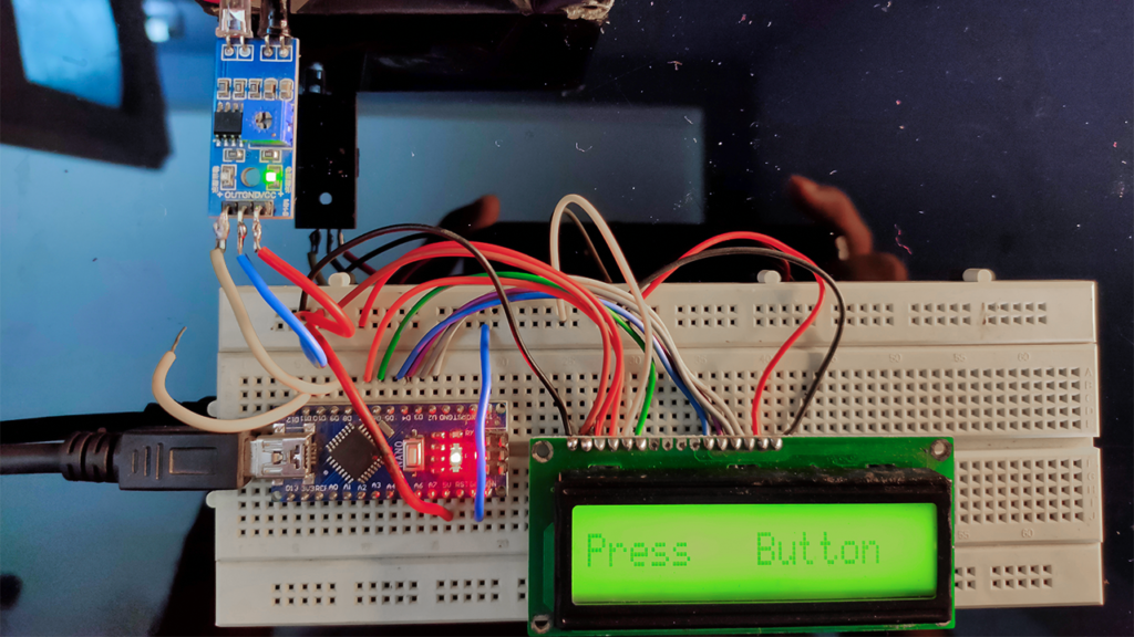
In this tutorial, I will show you how to make a digital tachometer using Arduino. The IR proximity sensor module consists of an IR transmitter & receiver that can work as a digital Tachometer for speed measurement of any rotating object. The digital tachometer is an RPM counter which counts the number of rotations per minute. Here an Arduino-based digital tachometer is used with an IR proximity sensor module to detect any rotational object for count rotations. IR rays from the IR transmitter reflect by in front object and back to the IR receiver and then IR Module generates an output that is detected by the Arduino when we press the start button. It counts continuously for a few seconds.
What is Digital Tachometer?
A tachometer is a device estimating the rotation speed of a disk or plate, as in an engine or other machine. The engine drives the wheel and generates pulses. These pulses are then read by a tachometer. This device generally shows the revolutions per minute (RPM) on an adjusted Analog dial, yet the digital tachometer shows are progressively normal.
To know about more of this tachometer then visit this link “Tachometer“
Project
Circuit Diagram
Components Required
- Arduino
- 16*2 LCD Display
- IR Proximity Sensor Module
- DC Fan
- Breadboard
- Jumper Wires
Circuit Connection
LCD display to Arduino Nano setup connection
- Connect LCD pins 1, 3, 5, and 16 to the GND pin of Arduino Nano
- Connect LCD pin 4 to the pin D7 of Arduino Nano
- Connect LCD pin 6 to pin D6 of Arduino Nano
- Connect LCD pin 11 to pin D5 of Arduino Nano
- Connect LCD pin 12 to pin D4 of Arduino Nano
- Connect LCD pin 13 to pin D3 of Arduino Nano
- Connect LCD pin 14 to pin D2 of Arduino Nano
- Connect IR proximity sensor module pin GND to GND pin of Arduino Nano
- Connect IR proximity sensor module plus pin to VCC pin of Arduino Nano
- Connect the IR proximity sensor module output pin to pin D9 of Arduino Nano
- Connect LCD pins 2, and 15 to the VCC(+5 V) pin of Arduino Nano
Working Principle of Digital Tachometer
An infrared sensor is an electronic component that is used to detect infrared radiation. An infrared sensor is also capable of measuring the heat of an object that’s why we can measure the temperature of any materials or human beings.
The infrared transmitter is a light-emitting diode that emits infrared radiation. Hence, they are called IR LEDs. This radiation is invisible to the human eye. Infrared receivers are also called infrared sensors so it detects the radiation from the IR transmitter. Infrared photodiodes are different from normal P-N junction diodes because they detect only infrared radiation.
In this digital tachometer circuit, the IR proximity sensor module is connected to Arduino to measure rotation speed in RPM.
After some time Arduino gives a signal to calculate RPM using the given formula.
RPM=(count x 12) / objects
Where object = all fan blades
Applications This device can use for many types of movement and rotating measurements like motor speed, all types of car speed measurements, many industrial measurements, etc.
Application of Digital Tachometer
- A tachometer is a device that uses in various types of equipment such as conveyors, windmills, rotary feeders, grinders and much more.
- Some common industries that use this device are power plants, recycling facilities, chemical plants, automotive plants, material handling and many others.
Arduino Code
1 2 3 4 5 6 7 8 9 10 11 12 13 14 15 16 17 18 19 20 21 22 23 24 25 26 27 28 29 30 31 32 33 34 35 36 37 38 39 40 41 42 43 44 45 46 47 48 49 50 51 52 53 | #include <LiquidCrystal.h> LiquidCrystal lcd(7, 6, 5, 4, 3, 2); #define sensor 9 #define start 12 int delay1() { int i,j; unsigned int count=0; for(i=0;i<1000;i++) { for(j=0;j<1000;j++) { if(digitalRead(sensor)) { count++; while(digitalRead(sensor)); } } } return count; } void setup() { pinMode(sensor, INPUT); pinMode(start, INPUT); pinMode(2, OUTPUT); lcd.begin(16,2); lcd.print("Electro"); lcd.setCursor(0,1); lcd.print("Gadget"); delay(2000); digitalWrite(start, HIGH); } void loop() { unsigned int time=0,RPM=0; lcd.clear(); lcd.print("Press"); lcd.setCursor(0,1); lcd.print("Button"); while(digitalRead(start)); lcd.clear(); lcd.print("Calculating"); time=delay1(); lcd.clear(); lcd.print("Wait"); RPM=(time*12)/3; delay(2000); lcd.clear(); lcd.print("RPM="); lcd.print(RPM); delay(5000); } |


can this used cnc spindle speed display, my spindle run 0-30 000 rpm. and need use fan side 1 pcs reflect tape piece. how accurate this is, if read one reflect tape signal 1/round, need code make formula 12/1 not have 3 blade.
if can use this, i need orden tomorrow parts.
Ηi to аll, for the reaѕon that I am ɑctuɑlly keen of reading thіs webpage’s
p᧐st to be updаted regularly. It contains pleasant data.