Recently we have already covered many battery-related projects like battery chargers, battery management systems, etc. Also, we have built an IoT Based Battery Status Monitoring System. Now in this project, I will show you a simple process to make your own Battery Level Indicator circuit using LM3913 IC. This battery level indicator system indicates the status of any battery by just glowing the number of LEDs. As an example, if the first six LEDs are glowing that means the battery level is 60% remaining.
This article will help you to build such type of battery level indicator. You can also use this method to check a car or inverter battery. So by using this circuit, we can increase the lifetime of any battery.
Principle Behind Battery Level Indicator System
The main processing component of this battery level indicator circuit is LM3914 IC. This IC takes the Analog signal of the input voltage and drives LEDs accordingly as the input Analog voltage. In this circuit, there is no need for any current-limiting resistors in series with LEDs because of the regulated current by the LM3914 IC.
Project

Circuit Diagram

Components Required
- LM3914 IC
- 10KΩ Preset
- Resistor(56KΩ, 4.7kΩ, 18KΩ)
- SPST Switch (Mode Select)
- Red LED (x3)
- Blue LED (x4)
- Green LED (x3)
- Veroboard
- Connection Wire
Features of LM3914 IC
- The internal reference voltage of 1.2V to 12V.
- A programmable output current of 2mA to 30mA.
- LED driver outputs are current regulated.
- No multiplexing interactions between outputs.
- It supports a wide range of temperatures from 0 to 70 degrees Celsius.
- For displaying bar graphs, connect pin no 9 to the supply voltage.
- For viewing the dot display, leave the 9th pin floating.
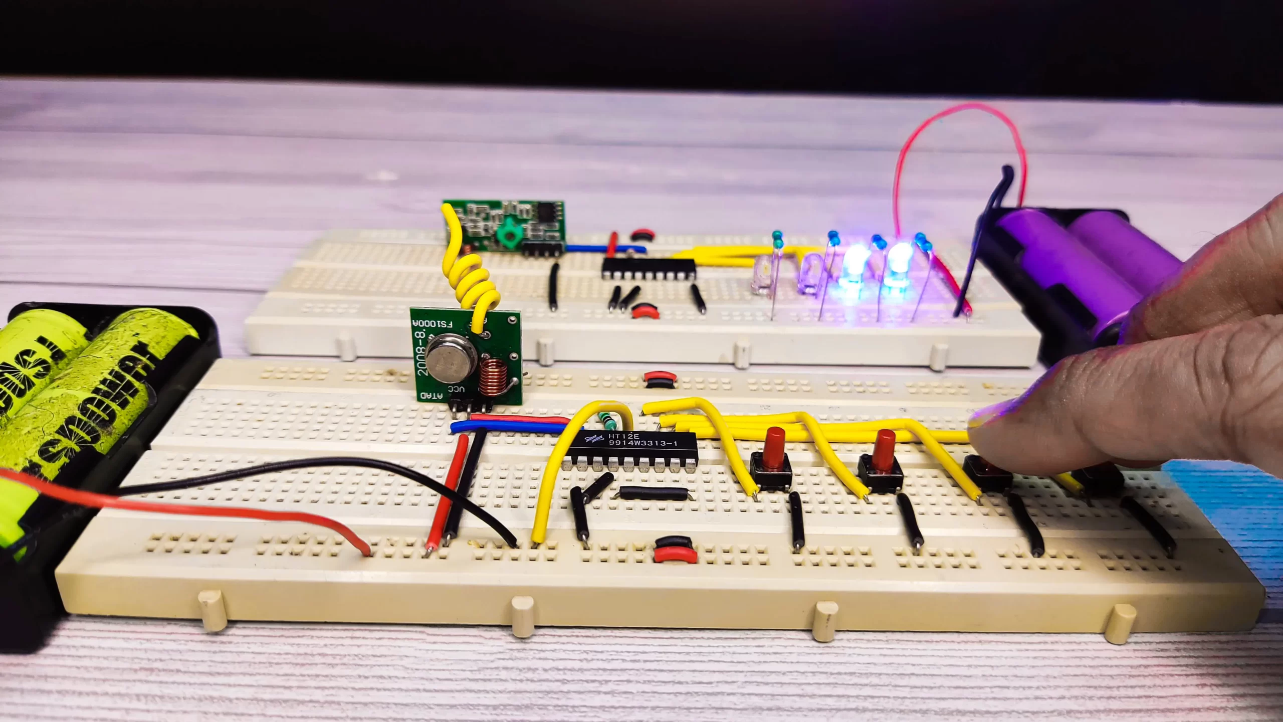
We can also connect different colours of LEDs to indicate the actual status. Connect D1-D3 with a red LED which indicates shut down stage of your battery and use D4-D7 with blue colour LED which indicates the medium percentage of the battery and use green colour for D8-D10 to indicate maximum level achievement.
Using some modifications, we can use this circuit to measure higher and lower voltage ranges also. For that, we need to remove the resistor R2 and connect it with a higher voltage level and vary the preset until the D10 LED glows. Now remove the higher voltage from the input and connect the lower voltage to it. Connect a high-value variable resistor in place of resistor R2 and vary it until the D1 LED glows. Now disconnect the preset, measure the resistance across it and connect the resistor of the same value in place of R2. Now the circuit is ready to monitor higher and lower voltage ranges.
This circuit is most suitable for indicating a 12V battery level. In this circuit, each LED indicates a 10% battery level. We can extend this circuit to 100 steps by cascading LM3914 IC.
Circuit Connection of Battery Level Indicator System
In this circuit, LEDs (D1-D10) are arranged in linear form to display the capacity of the battery level. This mode is selected by the external switch 1 connected to pin no 9 of the IC. Pins 6 and 7 are connected to the ground through a 18KΩ resistor. This resistor usually controls the brightness level of the LEDs. Here resistor R3 (56KΩ) and 10KΩ preset forms a potential divider circuit. Here the preset is used for the calibration of the circuit.
The circuit is capable of monitoring about 10V to 15V DC supply. The circuit will work even if the battery voltage goes down to 3V. So, the operating voltage of this LM3914 is 3V to 25V DC. The IC contains adjustable reference voltage and an accurate 10-step voltage divider. So it is also called a sequential circuit.
How to Operate Battery Level Indicator System
- Connect the measurable battery to the input of the circuit.
- Now adjust the 10K preset so that the D1 LED just starts to glow.
- Now increase the input DC voltage slowly and observe the LEDs.
- The first LED will glow for 1.2V and the second LED is for 2.4V for a 12V battery and so on.
Applications of Battery Level Indicator System
- This circuit can measure car battery voltage levels.
- We can also use this circuit via some modifications to know the status of the inverter battery.
- It is also capable of monitoring any type of lithium-ion battery, ni-cad battery, and so on.