In this project, we designed an IoT-based Battery Status Monitoring System using the ESP8266 NodeMCU board. Through this, we can monitor the total charging or discharging status along with battery voltage and percentage 24/7.
As we know, the battery is the most important electronics part for any portable devices as well as some non-portable devices. It powers the entire system where constant power is not reachable. So, it is important for us to monitor the voltage level of the battery, as excessive charging/discharging may lead to damage to the battery badly. Most electronic devices have a separate protection system called a Battery Management System (BMS). BMS monitors all the properties of the battery like the voltage, current, and temperature as well as control the auto-cut-off feature. This ensures the safety and proper handling of Lithium-Ion or Lithium Polymer batteries.
Due to some limitations, it only can monitor the battery’s health and indicates to the user accordingly. But the Internet of Things makes this problem easy for us. Now we can get directly notified about the battery status via smartphone from anywhere.
In this IoT-based Battery Monitoring System, we will use ESP8266 to send the battery status data to the Arduino IoT cloud server. Then the Arduino IoT will display the battery voltage along with the battery percentage in both the charging and discharging cases.
Must Read Top IoT Projects for Engineering Students
Project

Circuit Diagram

Components Required
- ESP8266 NodeMCU Board
- TP4056 Lithium-Ion Battery Charging Module
- 100KΩ Resistor (x2)
- Lithium-Ion Battery
- Veroboard
- Connection Wires
What is Lithium-Ion Battery?

The main component of our project is the lithium-ion battery. A lithium-ion battery or Li-ion battery is a type of rechargeable battery. Lithium-ion batteries are commonly used for portable electronics and electric vehicles.
During charging, lithium ions move from the positive electrode through an electrolyte to the negative electrode, and vice versa when discharging. Li-ion batteries use an intercalated lithium compound as the material at the positive electrode and typically graphite at the negative electrode. The batteries have a high energy density, no memory effect and low self-discharge.
Most Lithium-Ion batteries have a nominal voltage of 3.7V. When the battery gets the full charge, the maximum voltage is gone to around 4.2V. If you see the manufacturer datasheet, it is clearly mentioned that the cut-off voltage is 3V and varies depending on the battery type and applications. The battery I am using has a discharge cut-off voltage of 2.8V.
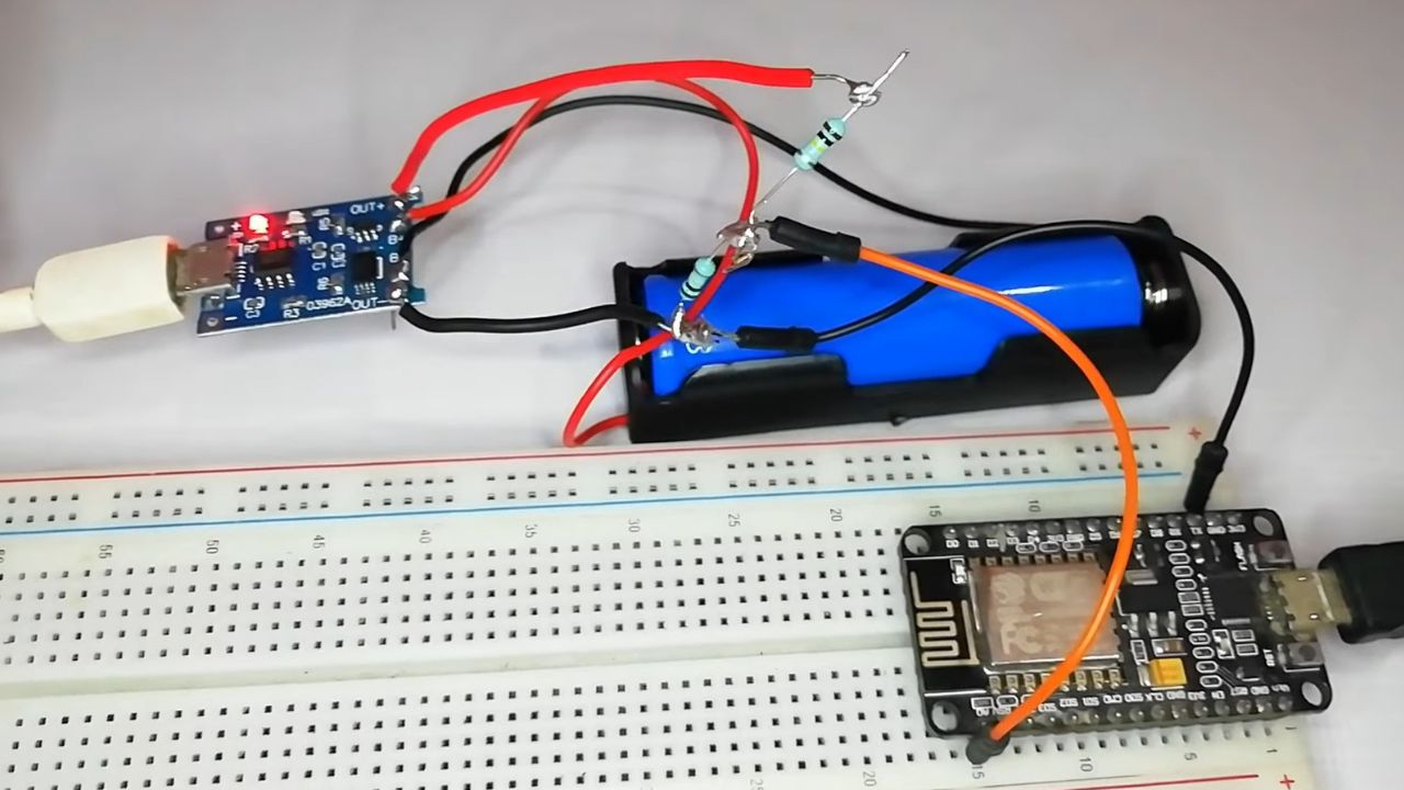
Circuit Connection of Battery Status Monitoring System
We will design and implement a battery monitoring system to monitor the battery health status along with voltage, charging, and discharging. We use NodeMCU ESP8266 Board here as the main microcontroller of this project. This WiFi module can interface with the WiFi network and uploads the data on a real-time basis to the server.
We also use the TP4056 (or MCP73831) battery charging module to charge our 3.7V Li-ion battery as it is suitable for a battery management system. Different types of BMS can also be used for this purpose.
The ESP8266 NodeMCU can support direct input Analog voltage of 0V-3.3V (A0 pin) as it has an inbuilt voltage divider circuit. But the voltage of the Li-Ion battery goes up to 4.2V. Hence we have to form a voltage divider network to lower the input voltage.
Voltage Divider Calculations
The maximum battery voltage is 4.2V and the cut-off voltage is 2.8V. Any values lesser than 3.3V will be easily supported by the ESP8266 analog pin (A0).
We have to first step down the upper voltage level for taking the analog value. The maximum battery voltage is 4.2V and there is a pair of 100KΩ resistors in series with the battery. This will give an output of 2.1V. Similarly, the minimum voltage is 2.8V as a cut-off voltage which steps down to 1.4V using the same voltage divider network. Now, both the upper and lower voltage is supported by the ESP8266 Analog pin.

Formula:
Vout=Vin×[R2 / (R1+R2)]
Setting Up Arduino IoT Dashboard for Battery Status Monitoring System
In order to display the battery status on the Arduino IoT server, we need to set up the Arduino IoT dashboard. First, visit Arduino IoT SSO. Create an account or sign in if you created it already. Then click on “Create Thing” and give it a title.
Now go to the Thing tab and create two global variables that are “bat_percentage” as an integer type and “voltage” as a floating-point number respectively by clicking “Add Variables”.
Now, we need to add our ESP8266 NodeMCU as a third-party device. To do that click on “Select Device” and then click on add third party device. Choose ESP8266 and select NodeMCU 1.0 ( ESP8266 12E). Click on continue and provide our device name.
Finally, click on the “Download PDF” button and save it securely for future use of the Device ID and Secret key.
Now we click on “Add network” and provide the WiFi SSID, Password, and Device Secret key. Then click on save to link our WiFi network. We need to build a computer dashboard as well as a mobile dashboard to visualize the real-time data. So, let’s move to the dashboard tab and create a new dashboard and named it “Battery Monitoring System”. Now click on “Add” to add widgets to your dashboard. In this tutorial, we will use one gauge, one percentage, and two chart widgets to display our data on the dashboard.
The First widget (Gauge is for monitoring the battery voltage level. So we will name it “Battery Voltage” and link the “voltage” float-point variable from the Things tab that we created earlier. Similarly, for “Battery Percentage”, we will link a “bat_percentage” integer variable from the Things tab.
Finally, we need to configure one chart widget for “Battery Voltage” and another for “Battery Percentage” and link those with “voltage” and “bat_percentage” variables respectively. Now we have created our final dashboard. Now let’s go to program our NodeMCU ESP8266 to send the data to the Arduino IoT Cloud server.
Upload The ESP8266 Code Using Arduino IoT Website
The advantage of using Arduino IoT Cloud is, that you can program your ESP8266 board from the Arduino IoT website directly. You don’t need any separate software like Arduino IDE. Simply install and run “Arduino Create Agent” and upload your code through this. That’s it.
After that, return to the Things tab and click on the sketch option. Simply, copy and paste the below code and compile it. Then upload the code to your NodeMCU board accordingly.
Calibrate Analog Voltage Value
The circuit is designed to fix 100KΩ pair of resistors. But most of the resistors have a tolerance of ±5%. Because of this resistor values may be between 95KΩ to 105KΩ. As a result, the output voltage and the Analog signal output both will be affected.
In order to fix this, we can compare the voltage difference between the serial monitor reading and the multimeter reading. Test the actual output voltage at the TP4056 output terminal using a multimeter.
Subtract the multimeter voltage value from the value obtained on the serial monitor.
In the following line of the code add this calibration factor.
This will fix any error in the voltage reading. So this is how we can design an IoT-Based Battery Status Monitoring System using ESP8266 and get the reading on Arduino IoT Cloud Server. In case you want a 99% accurate battery status monitoring system, you can use MAX17043 fuel gauge IC which removes all the limitations of measuring battery percentage by this method.
How to Install ESP8266 Board Manager?
Click on the “File” from the Arduino IDE. Then click on “Preference”. From the additional board manager, you have to paste this URL: https://arduino.esp8266.com/stable/package_esp8266com_index.json. After that click on “Tools→Board→Boards Manager→Type ESP8266 and install.
ESP8266 Source Code
#include <ESP8266WiFi.h>

String apiKey = "**************";
const char* ssid =  "**************";     // Enter your WiFi Network's SSID
const char* pass =  "**************"; // Enter your WiFi Network's Password
const char* server = "api.thingspeak.com";

int analogInPin  = A0;    // Analog input pin
int sensorValue;          // Analog Output of Sensor
float calibration = 0.36; // Check Battery voltage using multimeter & add/subtract the value
int bat_percentage;

WiFiClient client;

void setup()
{
  Serial.begin(115200);
  Serial.println("Connecting to ");
  Serial.println(ssid);
  WiFi.begin(ssid, pass);

  while (WiFi.status() != WL_CONNECTED)
  {
    delay(100);
    Serial.print("*");
  }
  Serial.println("");
  Serial.println("WiFi connected");
}

void loop()
{
  sensorValue = analogRead(analogInPin);
  float voltage = (((sensorValue * 3.3) / 1024) * 2 + calibration); //multiply by two as voltage divider network is 100K & 100K Resistor

  bat_percentage = mapfloat(voltage, 2.8, 4.2, 0, 100); //2.8V as Battery Cut off Voltage & 4.2V as Maximum Voltage

  if (bat_percentage >= 100)
  {
    bat_percentage = 100;
  }
  if (bat_percentage <= 0)
  {
    bat_percentage = 1;
  }

  Serial.print("Analog Value = ");
  Serial.print(sensorValue);
  Serial.print("\t Output Voltage = ");
  Serial.print(voltage);
  Serial.print("\t Battery Percentage = ");
  Serial.println(bat_percentage);
  delay(1000);

  if (client.connect(server, 80))
  {

    String postStr = apiKey;
    postStr += "&field1=";
    postStr += String(voltage);
    postStr += "&field2=";
    postStr += String(bat_percentage);
    postStr += "\r\n\r\n";

    client.print("POST /update HTTP/1.1\n");
    delay(100);
    client.print("Host: api.thingspeak.com\n");
    delay(100);
    client.print("Connection: close\n");
    delay(100);
    client.print("X-THINGSPEAKAPIKEY: " + apiKey + "\n");
    delay(100);
    client.print("Content-Type: application/x-www-form-urlencoded\n");
    delay(100);
    client.print("Content-Length: ");
    delay(100);
    client.print(postStr.length());
    delay(100);
    client.print("\n\n");
    delay(100);
    client.print(postStr);
    delay(100);
  }
  client.stop();
  Serial.println("Sending....");
  delay(15000);
}

float mapfloat(float x, float in_min, float in_max, float out_min, float out_max)
{
  return (x - in_min) * (out_max - out_min) / (in_max - in_min) + out_min;
}