Are you looking for a perfect Arduino Line Follower Car for your engineering projects? But don’t know how to build it? Okay, no problem I have discussed a detailed step-by-step guide on how you can build this awesome project for you.
When we talk about simple robotics technology that is operated through any kind of microcontroller, then a popular name is come out i.e., a Line Following Robot. It is a self-automated robotic technology that can detect a visual line on the floor. This is the line in which the robot can follow this and it should be a black line on a white surface (vice versa can be possible). At a certain advanced level, an upgraded line following robot can follow a magnetic field as the following path.
Large line following robots is used due to the automated production process in industries. It is not only used in industries but also in military applications, human assistance purposes, and also in delivery services, etc.
This is the best robotics project which beginner-level school and engineering students can easily build. In this project, we will be going to build a simple Arduino Line Following Robot with a few components.
Must Read Obstacle Avoiding Line Follower Robot
Project

Circuit Diagram
Components Required
- Arduino Nano
- L298N Motor Driver
- Geared Motors (x4)
- IR Sensor Module (x2)
- Electrical Tape (Black)
- Wires
- Chassis
- 3.7V Battery (x2)
- Battery Holder
Note: Here we are using a ready-made IR Sensor module, but you can use your own IR Sensor module. Here is the link to build your own “How to build an IR Sensor module“.
About Parts
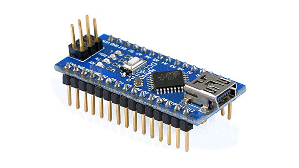
Arduino Nano

For the compact build, I choose Arduino Nano despite Arduino UNO. Arduino Nano is a small, flexible microcontroller board using an Atmega328p chip. It can also use as a substitute for UNO. All the functions are the same in these two boards. The size of its PCB is 18×45 mm. The clock speed is 16Mhz. Its input voltage is 5-12V. There are 30 pins including power pins, data pins, analog pins, and serial pins on this board.
Infrared Sensor

An infrared sensor is a device that detects infrared radiation emitted by nearby objects. It offers precise distance measurement, motion detection, and obstacle avoidance in various applications like robotics, security systems, and smart home devices.
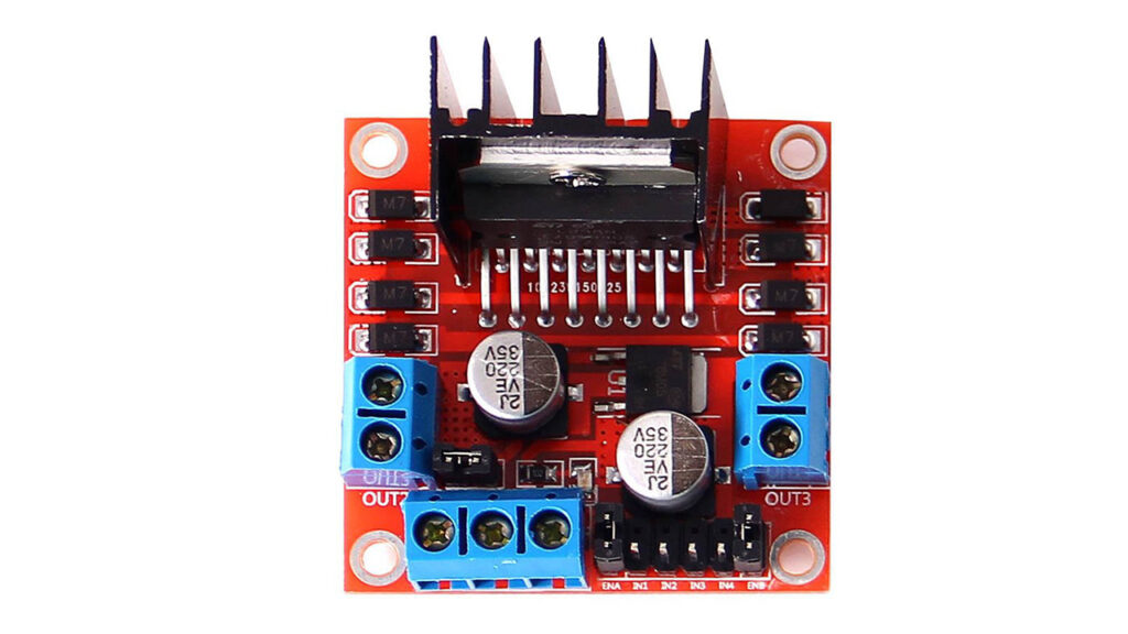
L298 Motor Driver

If you have selected the DC geared motors then you can either use the L298N driver module or an L293D driver module. Both are similar in work. The Difference is that L298N is more powerful than L293D. But in that case, we can use any of them.
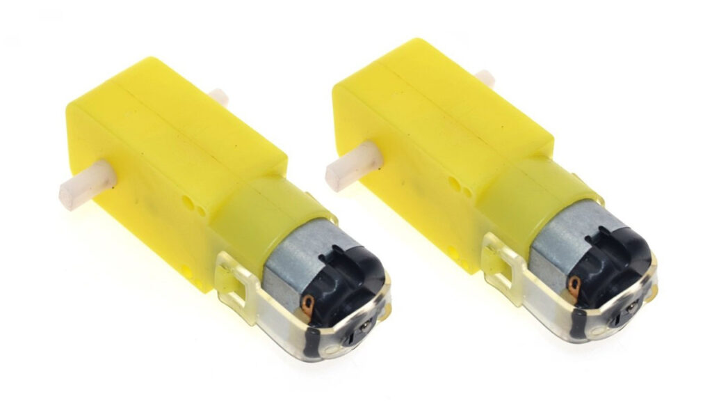
Motor

The best choice of motor that you can use for a line following robot, without a doubt will be a DC-geared motor. Yes, it is not mandatory to have a costly motor; the bot works fine with these cheap yellow-colored DC geared motors as well.
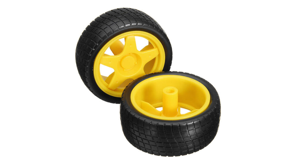
Wheel

I had a tough time figuring out that the problem was with my wheels. So make sure your wheels have a good grip over the floor you are using. Watch closely, your grip should never allow your wheels to skit on the floor.
Chassis

Another place where you should not compromise is with your robot’s chassis. You can use cardboard, wood, plastic anything that you are good with line following robot. But, just make sure the chassis is sturdy and should not wiggle when the robot is trying to run. I have designed my own chassis with cardboard.
Note: The power supply to the motors must be given from the motor driver IC. Hence, choose the appropriate power supply which is sufficient for all the components including the motors.
Working Principle of Arduino Line Following Robot
The working principle of this line following robot is too easy. It detects the black line on the surface and goes through that line accordingly. We explained a detailed work of this project below.
As mentioned in the above circuit diagram, we need two sensors to detect the line. For line detection logic, we used two infrared sensor modules, which consist of an IR Transmitter and an IR Receiver. So that whenever they come into proximity to a reflective surface, the light emitted by the IR Transmitter will be detected by the IR receiver.
As the reflectance of the light-colored surface is high, the infrared light emitted by the IR Transmitter will be maximumly reflected and will be detected by the IR Receiver.
In the case of the black surface, which has a low reflectance, the black surface completely absorbs the IR rays and doesn’t reach the IR Receiver.
Using the same principle, we will set up the IR Sensors on the line follower robot such that the two IR Sensors are on either side of the black line on the floor.
When the robot moves forward, both the sensors wait for the line to be detected. For example, if the IR Sensor 1 detects the black line, it means that there is a right curve (or turn) ahead.
Arduino detects this change and sends a signal to the motor driver accordingly. In order to turn right, the motor on the right side of the robot is slowed down using PWM, while the motor on the left side is run at normal speed.
Similarly, when the IR Sensor 2 detects the black line first, it means that there is a left curve ahead and the robot has to turn left. For the robot to turn left, the motor on the left side of the robot is slowed down (or can be stopped completely or can be rotated in the opposite direction) and the motor on the right side is run at normal speed.
Arduino continuously monitors the data from both the sensors and turns the robot as per the line detected by them.
Advantage of Arduino Line Following Robot
Building an Arduino line following robot offers numerous advantages. Firstly, it provides a hands-on learning experience in robotics and programming and problem-solving skills. Secondly, it introduces the concept of sensor-based navigation, allowing the robot to autonomously follow lines with high precision. Moreover, Arduino’s open-source platform offers a vast community and abundant resources for support and further development. Additionally, the affordability and accessibility of Arduino based modules make it a cost-effective choice for all hobbyists and beginners. Lastly, the versatility of Arduino allows for customization and expansion, enabling the robot to perform additional tasks beyond line following, such as obstacle avoidance or object detection.
Applications of Arduino Line Following Robot
- Line following robots are in use for automation processes in industries, military applications, etc.
- They are very useful as they can work without any supervision i.e. they work as automatic guided vehicles.
- With additional features like obstacle avoidance and other security measures, line follower robots can be used in driverless cars.
Arduino Source Code
1 2 3 4 5 6 7 8 9 10 11 12 13 14 15 16 17 18 19 20 21 22 23 24 25 26 27 28 29 30 31 32 33 34 35 36 37 38 39 40 41 42 43 44 45 46 47 48 49 50 51 52 53 54 55 56 57 58 59 60 61 62 63 64 65 66 67 68 69 70 71 72 73 74 75 76 77 78 79 80 81 82 83 84 85 86 87 88 89 90 91 92 93 94 95 96 97 98 99 | int mot1=6; int mot2=5; int mot3=4; int mot4=3; int left=A0; int right=A1; int Left=0; int Right=0; void LEFT (void); void RIGHT (void); void STOP (void); void setup() { pinMode(mot1,OUTPUT); pinMode(mot2,OUTPUT); pinMode(mot3,OUTPUT); pinMode(mot4,OUTPUT); pinMode(left,INPUT); pinMode(right,INPUT); digitalWrite(left,HIGH); digitalWrite(right,HIGH); } void loop() { analogWrite(mot1,255); analogWrite(mot2,0); analogWrite(mot3,255); analogWrite(mot4,0); while(1) { Left=digitalRead(left); Right=digitalRead(right); if((Left==0 && Right==1)==1) LEFT(); else if((Right==0 && Left==1)==1) RIGHT(); } } void LEFT (void) { analogWrite(mot3,0); analogWrite(mot4,30); while(Left==0) { Left=digitalRead(left); Right=digitalRead(right); if(Right==0) { int lprev=Left; int rprev=Right; STOP(); while(((lprev==Left)&&(rprev==Right))==1) { Left=digitalRead(left); Right=digitalRead(right); } } analogWrite(mot1,255); analogWrite(mot2,0); } analogWrite(mot3,255); analogWrite(mot4,0); } void RIGHT (void) { analogWrite(mot1,0); analogWrite(mot2,30); while(Right==0) { Left=digitalRead(left); Right=digitalRead(right); if(Left==0) { int lprev=Left; int rprev=Right; STOP(); while(((lprev==Left)&&(rprev==Right))==1) { Left=digitalRead(left); Right=digitalRead(right); } } analogWrite(mot3,255); analogWrite(mot4,0); } analogWrite(mot1,255); analogWrite(mot2,0); } void STOP (void) { analogWrite(mot1,0); analogWrite(mot2,0); analogWrite(mot3,0); analogWrite(mot4,0); } |
Conclusion
In conclusion, the Arduino line following robot offers an exciting opportunity to the world of robotics. With its versatile capabilities and simple programming, it provides an excellent platform for learning and experimentation. By mastering the art of line following, you can develop valuable skills in sensor integration, motor control, and algorithm design. Whether you’re a hobbyist or an engineer, building an Arduino line following robot opens doors to endless possibilities and sparks creativity in the field of robotics. Get ready to embark on a thrilling journey of exploration and innovation.
FAQs on Arduino Line Following Robot
An Arduino line following robot is a small robotic vehicle that uses sensors to detect and follow a line mapped on the ground. It is programmed using Arduino boards, allowing for customization and flexibility in its behaviour.
The robot utilizes line detection sensors, such as infrared sensors, to detect the contrast between the line and the background. By analyzing the sensor readings, it adjusts its movements to stay on the line, typically using motor control.
Arduino line following robots find applications in various fields, including educational projects, robotics competitions, automated industrial processes, and research experiments. They serve as a foundation for learning about robotics, automation, and sensor integration.
Yes, one of the advantages of using Arduino boards is the ability to program and customize the behavior of the line following robot. You can modify the code to implement advanced features, such as obstacle avoidance or speed control.
Yes, the Arduino line following robot is an excellent starting point for beginners in robotics. They offer a hands-on learning experience in electronics, programming, and robotics concepts while being relatively easy to build and program.
Typical components include an Arduino board (e.g., Arduino Uno), line detection sensors (e.g., infrared or colour sensors), a motor driver module, motors, wheels, a power supply, and a chassis for the robot.
Yes, there are numerous online resources, tutorials, and video guides available that provide step-by-step instructions on building and programming Arduino line following robots. Websites like Electro Gadget, YouTube, and robotics communities are great places to start.
