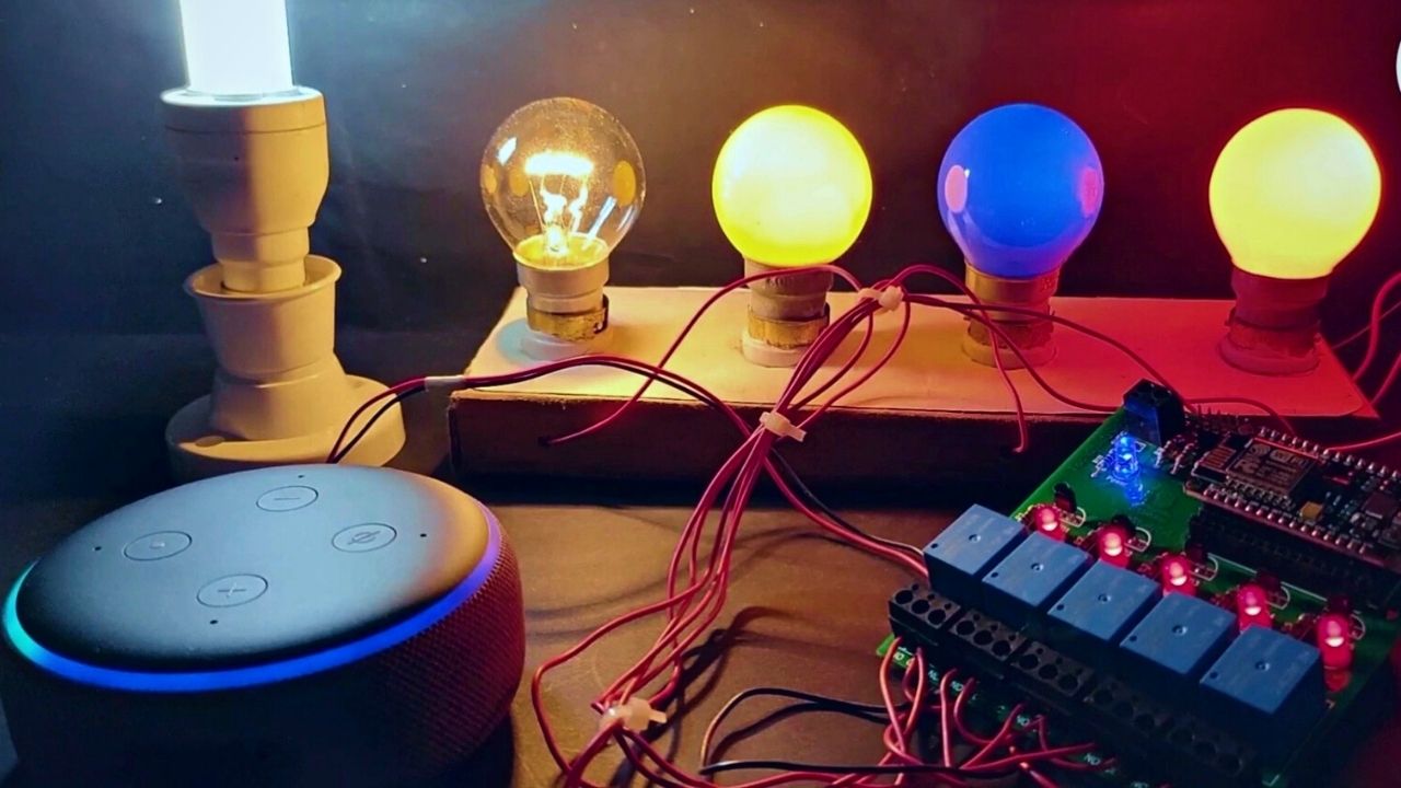
In this project, we are going to build an Alexa Home Automation System with Arduino IoT cloud. Here we use the ESP8266 NodeMCU module. With the help of this project, we can operate 4 home appliances (Can be modified according to your needs) through Arduino IoT Cloud dashboard, Alexa and mechanical switches. We can also operate this system by controlling the relays from the Alexa app from any place in the world. Internet issue is very common in rural areas. So if there is no internet you can operate those appliances by manual switches.
In this project, we do not need to buy any Alexa devices or Amazon Echo Dot for this home automation system. Because I made this project using all free tools.
You just need to follow all the steps carefully. After this, you can easily make an Alexa Smart Home System with Arduino IoT Cloud and Amazon Alexa to control the appliances with your voice commands.
Must Read Home Automation Projects
Project

Circuit Diagram

Components Required
- ESP8266 NodeMCU (ESP32)
- 5V Relay (x4)
- BC547 Transistor (x4)
- 1N4007 PN Diode (x4)
- Green LED (x4)
- Red LED (x4)
- 1K Resistor (x4)
- 100 Ohm Resistor (x8)
- Push Button (x4)
- Bulb (x4)
- 5V DC Source
- 220V AC Source
Circuit Connection
This circuit connection is very easy for this project. We used D1, D2, D5 and D6 GPIO pins to control the 4-channel relay module. The SD3, D3, D7, and RX are connected with the push buttons to control this project manually.
The INPUT_PULLUP function in Arduino IDE is used here instead of using pull-up resistors with each switch. From the source code, when the control pins of the relay modules receive a LOW signal, the relay will turn on and for the HIGH signal it will turn off.
Here supply is a 5V 2Amp adopter.
Steps to Build Alexa Home Automation System
- First, create an account in Arduino IoT Cloud.
- Make all set up for Dashboard.
- Set up Arduino IoT Cloud for ESP8266.
- Program NodeMCU with Arduino IDE.
- Connection of IoT Cloud and Alexa application.
Sign Up for Arduino IoT Cloud Free account
For this home automation project, I explained to you how to set up a free Arduino IoT Cloud account. This setup connects ESP8266 to control appliances with Alexa.
Create An Arduino IoT Cloud
- In this step, I explained to you how to create an Arduino IoT Cloud account. First, you have to go to the following link
https://create.arduino.cc/iot/things. - Click on Create One.
- Enter all the required details it wants. Then click Next.
- On the next page, it requires an email, username and password for your
Arduino IoT Cloud account. After filling in all of these, you have to agree to all terms and conditions. - Now click on the Sign Up button.
- Then check your email. The verification email will be sent to your account. Click the link in the email and verify it.
- Then return to the Arduino IoT Cloud and refresh the page.
- At last click on the IoT Cloud.
Steps to Add Device
- Click on select device.
- Then click on set up a Third Party Device.
- Now select the device (ESP8266) and select the model (NodeMCU 1.0).
- There you can see all Arduino Cloud-compatible boards in the menu.
- Click on Continue.
- Enter a name for your device and click on Next.
- After that, you get the ID and secret key for your device. You can save details by clicking on download the PDF.
- At last, click Continue and your device will be added.
Steps to Add Variable in Arduino IoT Cloud Projects
To control sensors or relays, you have to get data from these. This data can be captured by variables. In this project, we need four variables. For a free plan, you can add upto five variables.
- Click on Add Variables.
- Name the variable and select the type as Alexa compatible switch.
- Click on Variable Permission as Read and Write and update policy as On Change
- Click Add Variables.
- In this process, you can add all types of Variables.
Creating Web Dashboard for Arduino IoT Cloud
- First, click on Dashboard and then ‘Build Dashboard’.
- Click on the edit button. Then click Add and there you can select the switch widget.
- Then came the switch and click the Link Variable button which is visible on the right.
- As we already create a variable in the previous step. Link this with the widget.
- Now click on Link Variable. Then click Done.
- Now you can add all the required widgets. In this project, we need four Switch widgets. After adding this, click on Things to exit the dashboard.
Sketch for Arduino IoT Cloud
After adding any variable to this, it will automatically be saved in the sketch tab. If you want to edit this further. You can open a full editor. From there you can download the sketch of the program for the microcontroller. For this project, the downloaded sketch is opened in Arduino IDE.
Installing Libraries
- In this step, we are going to install all libraries and other dependencies. In this project, we need a library for ESP8266.
- First, go to the sketch button.
- Then click include Libraries.
- Click manage libraries in Arduino IDE.
- There it will ask to install all dependencies. Click on Install All.
How to Update Project Sketch
To update the Sketch, open the .ino file in Arduino IDE. There you can enter the Thing ID, Device ID, WiFi credentials and Secret Key.
You can copy the Thing ID from the right corner of this window. Now paste the Thing ID and Device ID in the thingProperties.h file in Arduino IDE. Then paste WiFi credentials and the Secret key in the arduino_secrets.h file.
Now upload the code for ESP8266 in Arduino IDE.
How to Use Arduino Cloud Remote
First, install the ‘Arduino IoT Cloud Remote’ from Google Play Store. Then sign In to the app with the email which you use in the Arduino IoT Cloud account. Enter the Thing name to open the dashboard.
Program ESP8266 NodeMCU
- At first, Update the Preferences –> Aditional boards Manager URLs: https://dl.espressif.com/dl/package_esp32_index.json, and http://arduino.esp8266.com/stable/package_esp8266com_index.json
- Then install the ESP8266 board from the Board manager.
- Then install all required libraries and dependencies.
NodeMCU Code Alexa Home Automation System
When you upload the code to ESP8266, you can connect the Alexa app with it. The steps to connect Arduino IoT Cloud account with Amazon Alexa app in the following.
#include "arduino_secrets.h"
#include "thingProperties.h"
// define the GPIO connected pins with relays and switches
#define RelayPin1 5  //D1
#define RelayPin2 4  //D2
#define RelayPin3 14 //D5
#define RelayPin4 12 //D6
#define SwitchPin1 10  //SD3
#define SwitchPin2 0   //D3
#define SwitchPin3 13  //D7
#define SwitchPin4 3   //RX
#define wifiLed   16   //D0
int toggleState_1 = 0; //Define integer to remember the toggle state for relay 1
int toggleState_2 = 0; //Define integer to remember the toggle state for relay 2
int toggleState_3 = 0; //Define integer to remember the toggle state for relay 3
int toggleState_4 = 0; //Define integer to remember the toggle state for relay 4
void relayOnOff(int relay) {
  switch (relay) {
    case 1:
      if (toggleState_1 == 0) {
        digitalWrite(RelayPin1, LOW); // Turn on relay 1
        toggleState_1 = 1;
        Serial.println("Device1 ON");
      }
      else {
        digitalWrite(RelayPin1, HIGH); // Turn off relay 1
        toggleState_1 = 0;
        Serial.println("Device1 OFF");
      }
      delay(100);
      break;
    case 2:
      if (toggleState_2 == 0) {
        digitalWrite(RelayPin2, LOW); // Turn on relay 2
        toggleState_2 = 1;
        Serial.println("Device2 ON");
      }
      else {
        digitalWrite(RelayPin2, HIGH); // Turn off relay 2
        toggleState_2 = 0;
        Serial.println("Device2 OFF");
      }
      delay(100);
      break;
    case 3:
      if (toggleState_3 == 0) {
        digitalWrite(RelayPin3, LOW); // Turn on relay 3
        toggleState_3 = 1;
        Serial.println("Device3 ON");
      } else {
        digitalWrite(RelayPin3, HIGH); // Turn off relay 3
        toggleState_3 = 0;
        Serial.println("Device3 OFF");
      }
      delay(100);
      break;
    case 4:
      if (toggleState_4 == 0) {
        digitalWrite(RelayPin4, LOW); // Turn on relay 4
        toggleState_4 = 1;
        Serial.println("Device4 ON");
      }
      else {
        digitalWrite(RelayPin4, HIGH); // Turn off relay 4
        toggleState_4 = 0;
        Serial.println("Device4 OFF");
      }
      delay(100);
      break;
    default : break;
  }
}
void manual_control() {
  //Manual Switch Control
  if (digitalRead(SwitchPin1) == LOW) {
    delay(200);
    relayOnOff(1);
  }
  else if (digitalRead(SwitchPin2) == LOW) {
    delay(200);
    relayOnOff(2);
  }
  else if (digitalRead(SwitchPin3) == LOW) {
    delay(200);
    relayOnOff(3);
  }
  else if (digitalRead(SwitchPin4) == LOW) {
    delay(200);
    relayOnOff(4);
  }
}
void setup() {
  // Initialize serial and wait for port to open:
  Serial.begin(9600);
  delay(1500);
  // Define thingProperties.h
  initProperties();
  // Connect to Arduino IoT Cloud

  ArduinoCloud.begin(ArduinoIoTPreferredConnection);
  setDebugMessageLevel(2);
  ArduinoCloud.printDebugInfo();
  pinMode(RelayPin1, OUTPUT);
  pinMode(RelayPin2, OUTPUT);
  pinMode(RelayPin3, OUTPUT);
  pinMode(RelayPin4, OUTPUT);
  pinMode(wifiLed, OUTPUT);
  pinMode(SwitchPin1, INPUT_PULLUP);
  pinMode(SwitchPin2, INPUT_PULLUP);
  pinMode(SwitchPin3, INPUT_PULLUP);
  pinMode(SwitchPin4, INPUT_PULLUP);
  //During Starting all Relays should TURN OFF
  digitalWrite(RelayPin1, HIGH);
  digitalWrite(RelayPin2, HIGH);
  digitalWrite(RelayPin3, HIGH);
  digitalWrite(RelayPin4, HIGH);
  digitalWrite(wifiLed, HIGH);  //Turn OFF WiFi LED
}
void loop() {
  ArduinoCloud.update();

  manual_control(); //Control relays manually
  if (WiFi.status() != WL_CONNECTED)
  {
    digitalWrite(wifiLed, HIGH); //Turn OFF WiFi LED
  }
  else{
    digitalWrite(wifiLed, LOW); //Turn ON WiFi LED
  }
}
void onSwitch1Change() {
  if (switch1 == 1)
  {
    digitalWrite(RelayPin1, LOW);
    Serial.println("Device1 ON");
    toggleState_1 = 1;
  }
  else
  {
    digitalWrite(RelayPin1, HIGH);
    Serial.println("Device1 OFF");
    toggleState_1 = 0;
  }
}
void onSwitch2Change() {
  if (switch2 == 1)
  {
    digitalWrite(RelayPin2, LOW);
    Serial.println("Device2 ON");
    toggleState_2 = 1;
  }
  else
  {
    digitalWrite(RelayPin2, HIGH);
    Serial.println("Device2 OFF");
    toggleState_2 = 0;
  }
}
void onSwitch3Change() {
  if (switch3 == 1)
  {
    digitalWrite(RelayPin3, LOW);
    Serial.println("Device2 ON");
    toggleState_3 = 1;
  }
  else
  {
    digitalWrite(RelayPin3, HIGH);
    Serial.println("Device3 OFF");
    toggleState_3 = 0;
  }
}
void onSwitch4Change() {
  if (switch4 == 1)
  {
    digitalWrite(RelayPin4, LOW);
    Serial.println("Device4 ON");
    toggleState_4 = 1;
  }
  else
  {
    digitalWrite(RelayPin4, HIGH);
    Serial.println("Device4 OFF");
    toggleState_4 = 0;
  }
}How to connect the Amazon Alexa app With ESP8266
- At first, click on More in the Amazon Alexa app.
- Then select Skills and Games.
- In the search option, you can find Arduino.
- Click Enable To Use.
How to Add Device to Alexa App
- In the Alexa app, sign in with the email and password which you used to log in to your Arduino IoT Cloud Account.
- Then Close it.
- Click on Discover Devices. Your device name is visible there in a few seconds.
- Then click on your device. Then select all the switches.
- If ESP8266 is connected to your WiFi, you can control all appliances from the Alexa app.
- Now you just need to say “Alexa, Turn On the light”. The light is on. With this voice command, you can control appliances with your voice.
How to Use This Project Manually
You can control appliances with push buttons. If you have no WiFi or internet connection, you can control it manually using this method.
Features of This Project
- You can On/Off switches and smart plugs using your voice.
- Increase or decrease the brightness of your room lights.
- You can also change the colour of the lights.
- You can check the room temperature with sensors.
- See motion activity from sensors in your room.


Check out this project https://circuitdiagrams.in/4-channel-ir-remote-control-system
Hello. Sir. Do you have a project with transmitter 4 button push button and receiver 4 led?