Smart energy monitoring systems are becoming increasingly popular these days to increase the energy efficiency of industries, buildings, etc. We have previously built an energy monitoring system to monitor power reading through a cloud server. But now we are going to build an Arduino-based smart energy monitoring system for AC current measurement. We have also seen AC current measurement multimeters from professional technicians which can measure current efficiently very efficiently. But these meters are so costly and also we can’t monitor the current all the time with this.
For this drawback, today in this project we are going to build an Arduino-based system that can detect current all the time, and display the result through an LCD display. And it is cost-effective. We are using CT (Current Transformer) sensor to measure current efficiently. This circuit also uses a rectifier and an amplifier for signal conditioning. For displaying the current we use a 16×2 LCD display. There are also many different ways to make this system like an Inductive sensor, Hall-Effect sensor, etc which we will discuss in another project. CT sensor can measure current range from 100mA to 100Amp.
Project

Circuit Diagram

Components Required
- Arduino Nano
- SCT-013 CT Sensor
- LM358 Op-Amp
- 16×2 LCD Display
- I2C Display Module
- Resistor (10K, 22K, 1K)
- 100uF/25V Electrolyte Capacitor
- 1N5819 Schottky Diode
- Breadboard
- Wires
- 5 Volt Power Supply
Current Transformer for AC Current Measurement
The Current Transformer (CT) is a very safe method for measuring alternating current as there is no physical connection between the main AC current and the circuit. It is used in industries and large complexes where a large number of current needs to be measured. It is a type of “Instrument Transformer” that is made to produce an alternating current in its secondary winding coil which is proportional to the current being measured in its primary coil. Current Transformer reduces high voltage currents to a much minimal current and provides a convenient way of safely monitoring the actual electrical current flowing through an AC transmission line.
Unlike the voltage transformer, the Current Transformer consists of very few turns of the coil as its primary winding. This primary winding can be of either a single flat turn or just a conductor or bus bar placed through a central hole. There are three types of Current Transformers exist Wound Current Transformers, Toroidal Current Transformers, and Bar-type Current Transformers. In this project, we are using Toroidal Current Transformer.
SCT-013 Current Transformer Sensor

This is a Non-Invasive current sensor that has been used to sense the accuracy of the current measurement. SCT-013 is a split-core clamp-on CT sensor. Because of this feature, the CT has been clamped onto the single phase of the wire. In the output section, an AC voltage is engaged in direct proportion to the AC current change in the single phase.
How to Calculate Current Ratio for AC Current Measurement
If a magnetic field is enclosed around a closed loop of wire, the value of the integral is equal to the net current enclosed by the loop. The primary coil of the Current Transformer has the main wire with the current we need to measure passed through the centre of the core. The primary coil that carries the main current is said to have a single loop. The wire produces the magnetic field that drives the current on the secondary winding, which is used as the output of the CT sensor.
The current on the secondary winding is proportional to the current flowing through the centre of the core. Let’s suppose the current on the centre core is 20 amps and in the secondary coil with a 20 milliamps ratio. It means that 20 amps on the primary circuit would produce 20 milliamps on the secondary coil.
Current Ratio
Turns Ratio = Np / Ns = Is / Ip
Where,
Np = Turns in the primary winding
Ns = Turns in the secondary winding
Ip = Current in the primary winding
Is = Current in the secondary winding
Now we need to calculate the Ns.
Let’s consider the current ratio as 20A:20mA.
Is = 20mA , Ip = 20A = 20000mA, Np = 1
Ns = (Np * Ip) / Is
Ns = (1 * 20000) / 20
So, Ns = 1000 turns
Burden Resistance for AC Current Measurement
Another important passive component is burden resistance which protects the CT sensor under open-circuit conditions. This is connected across the secondary coil of the current transformer. To avoid high voltage protection, the secondary coil or winding should always be in close circuit condition. But due to an incorrect connection of the circuit, a high voltage will be created across the secondary terminal. By using burden resistance, this type of error will be solved.
Working Principle of AC Current Measurement Circuit
Now we are going to discuss how this circuit will actually work. Firstly, connect the load to with AC mains supply and pass any one of the load’s wires (Either line or neutral but don’t pass both of them) through the middle of the CT sensor. This wire acts as the primary winding for the current transformer.
Due to the presence of AC current in the primary wire, AC voltage is induced in the secondary winding as well. Now to convert this AC voltage into DC voltage, a half-wave rectifier is used. This half-wave rectifier is in forward biased in the positive half cycle and reversed bias in the negative half cycle.
To rectify the ripples and get a smooth DC voltage, we added a capacitor at the output of the half-wave rectifier. The output voltage that is obtained from the rectifier circuit is of very less magnitude, so we use an LM358 operational amplifier with a feedback resistor.
The output of the non-inverting op-amp is:
Vout = (Rf / R1 + 1 ) Vin
Where,
Rf = feedback resistor value i.e., 10K
R1 = 1K
Vout = output voltage of LM358
Vin = applied voltage of non-inverting terminal of op-amp
So, Vout = (10 / 1 + 1 ) Vin = (11 * Vin)V
Arduino Code
A library needs to download LiquidCrystal_I2C.
#include <Wire.h>
#include <LiquidCrystal_I2C.h>
LiquidCrystal_I2C lcd(0x27, 16, 2);
int current=A1;
int readValue;
float Value;
float Voltage;
void setup()
{
lcd.init()
lcd.backlight();
pinMode(current,INPUT);
}
void loop()
{
readValue = analogRead(current);
Voltage = (5./1023)*readValue;
Value = Voltage/10.680;
Serial.println(Value);
lcd.clear();
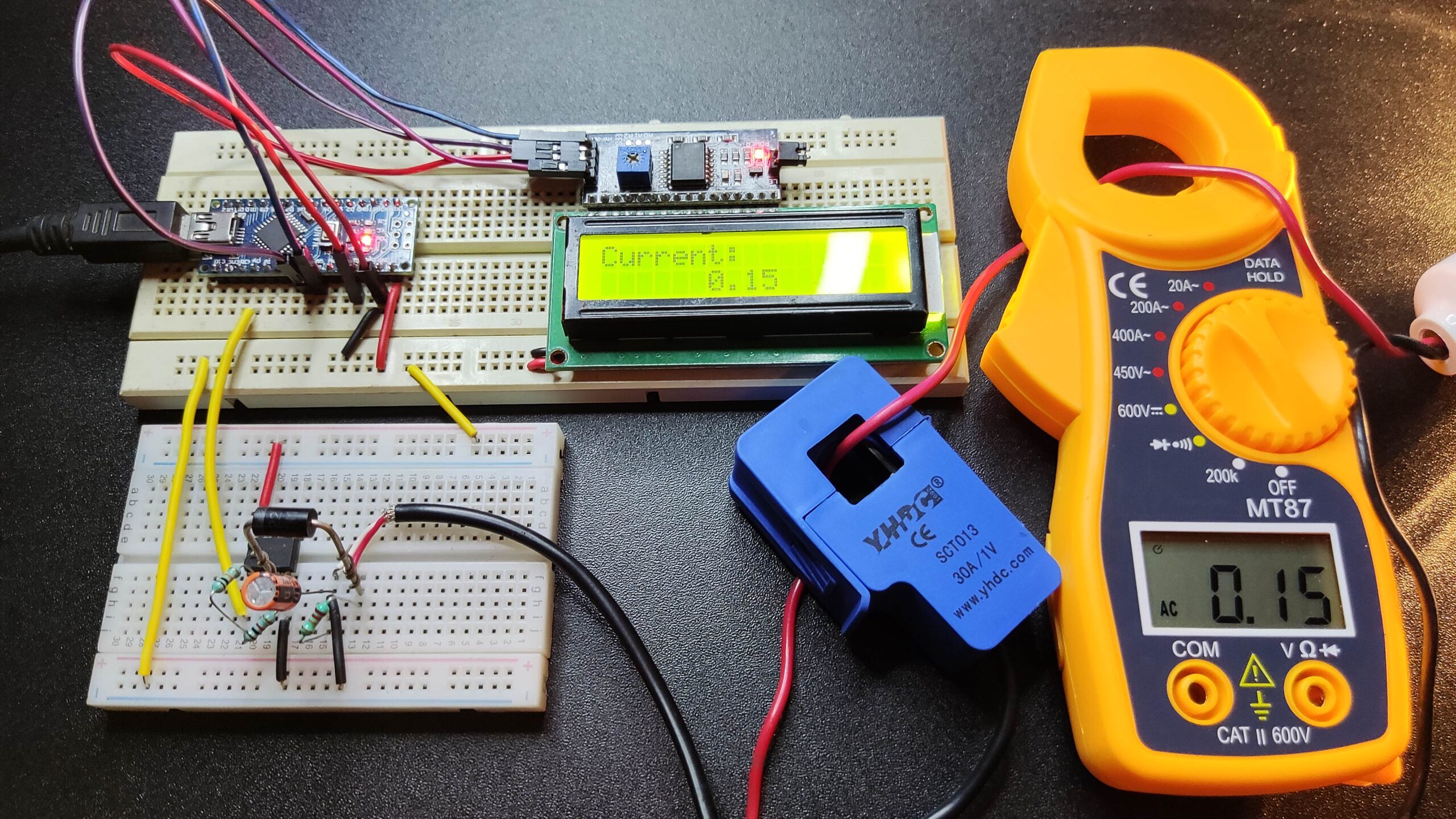
lcd.setCursor(0,0);
lcd.print("Current: ");
lcd.setCursor(6,1);
lcd.print(Value);
delay(1000);
}


What is the problem are you facing?
Define your problem.
avec un sct013 100A/50mA le montage ne marche pas s’il vous plait aidée moi
SVP j’ai un SCT013 100A/50mA et une carte arduino uno Mais ca ne marche pas.