
In this project, an open-source and modular smart energy monitoring system is designed and implemented. A Wi-Fi-based IoT network has been designed which has the capability of monitoring daily energy consumption in our homes through our smartphones. In the IoT network, the current and voltage values have been measured with the current sensor SCT-013 (upto 100A) connected to the ESP32 development board. Real power, apparent power and power factors can be calculated by using measured current, voltage values and phase angle.
These measured and calculated values have been sent to the ESP32 development board by software serial method. The ESP32 provides the cloud server-based user interface where we can see these calculations and actual values. It uses a Wi-Fi access point connection. The user interface is displayed via the web browser and mobile application with TCP/IP protocols. Experimental studies prove that this system could be used in general-purpose applications such as IoT energy monitoring systems for smart home automation systems.
The demand for electricity is one of the most important things in our daily life to develop technology. A grid loading is made for two types of people, residential and commercial both. So operators have to do load distribution keeping in mind the two types of consumers. Smart Homes are designed with this in mind and to reduce energy consumption. Nowadays, smart homes have doing an important role in smart grids. Therefore, we need to control the energy consumption in those houses. Today, the Internet of Things (IoT) has captured a wide range of areas such as the automotive industry, logistics, hospitals, smart grids, metro cities and smart homes.
We can classify the IoT into two categories i.e., the Internet of Industrial Things (IIoT) and the Internet of Consumer Things (CIoT). In this project, CIoT systems have been discussed in brief. In our home, energy consumption could be easily monitored by controlling the home appliances like water geysers, air conditioners, dishwashers and other systems by using IoT. Traditional measuring methods are known to be labour-intensive and complex for practical applications. Using CIoT systems with Wi-Fi-enabled devices cuts out these problems with one click. Most homes have Wi-Fi networks, computers and smartphones in today’s innovative world. So it is also easier now.
Must Read Home Automation Projects
Principle Behind Smart Energy Monitoring System
In this project, the SCT-013 current (CT) sensor is used for single-phase current measurement, and a 9V AC step-down transformer is used to measure the RMS value of the voltage. These two sensors are connected to the ESP32 board. We can calculate power factor, real power and apparent power values using the measured current, RMS voltage values and phase angle in the Arduino IDE software.
The measured and calculated values have been sent to the development board by using Arduino IDE software. The ESP32, cloud server and smartphone device communicate with each other with TCP/IP protocol via a Wi-Fi access point in the designed CIoT network.
Project

Circuit Diagram

Components Required
- ESP32 Development Board
- SCT-012 Current Sensor
- ZMPT101B Voltage Sensor
- 10uF/25V Capacitor
- 10KΩ Resistor (x2)
- 100Ω Resistor
- 5 Volt Power Supply
- Connecting Wires
About Parts of The Smart Energy Monitoring System
ESP32 Development Board

It is a low-cost, minimal-power system on a microcontroller with integrated Wi-Fi and Bluetooth facility. ESP32 is created and developed by Espressif Systems, a Shanghai-based Chinese company, and it is manufactured by TSMC using its 40nm chip technology. In this project, we can use ESP8266 NodeMCU but there is only one analog pin that comes with it. And ESP32 have so many Analog pins. So according to our needs (Voltage and Current), we choose ESP32 in spite of ESP8266 NodeMCU.
Current Sensor (SCT-013)

This is a Non-Invasive current sensor that has been used to sense the accuracy of the current measurement. SCT-013 is a split-core clamp-on current sensor. Because of this feature, the CT has been clamped onto the single phase of the wire. In the output section, an AC voltage is engaged in direct proportion to the AC current change in the single phase.
Voltage Sensor

The 9V AC step-down transformer has been used here as a voltage sensor. But we could use ZMPT101B One-Phase Voltage Sensor for accurate sensing. It removes messy wire connections. But for reducing cost we use this method. The transformer provides insulation between high AC voltage and low AC voltage. The 9V transformer output terminal has been connected to the voltage divider circuit to bring this voltage to 0-5V. Thus voltage measurement can be made without requiring any high-voltage operation.
Circuit Connection for Smart Energy Monitoring System
Now let me discuss the circuit diagram of the CIoT-Based Smart Energy Monitoring System using the ESP32 IoT board. The circuit has been designed using EasyEDA software.
The connections are so simple. The ground pins of both modules are connected with the ground pin of the ESP32. The output Analog pin of the voltage sensor is connected to the GPIO35 of the ESP32. Similarly, the output Analog pin of the SCT-013 current sensor is connected to the GPIO34 of the ESP32. After that two 10KΩ resistors and a single 100Ω resistor are connected along with a 10uF/25V electrolyte capacitor.
The 16×2 LCD display is used in this project for looking more professional and good look. But since we are working on an IoT device, it will work even if we don’t have an LCD display. Here we also use a 16×2 I2C LCD module for ease to use. Connect the SDA and SCL terminals of the I2C module with the D21 and D22 pins of the ESP32 respectively.
Note: In case you want to connect the LCD display, just connect the pin numbers 4, 6, 11, 12, 13, 14 of the LCD display to the ESP32 development board pins D13, D12, D14, D27, D26, D25 pins. Finally connect the 1, 5, 16 pins of the LCD display to the ground and 2 and 15 pin to 5V VCC. You can use a 10K variable resistor at pin 3 of the LCD to adjust the contrast.
Apart from that, we need to measure the real-time AC voltage that is connected to the input AC terminal of the voltage sensor. Similarly, the current sensor clip doesn’t have any connections, just clip a phase or neutral wire and lock it. Don’t clip both phase and neutral wires otherwise the reading will go wrong.
Cloud Server Creation for Smart Energy Monitoring System
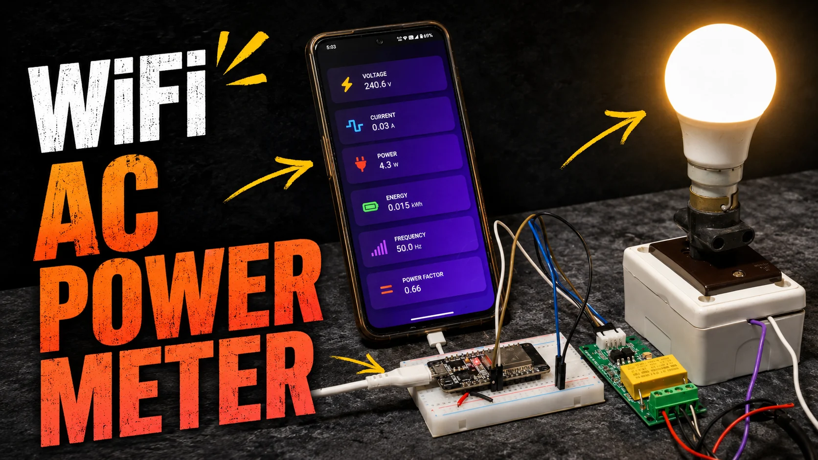
For this project, we use the Blynk application that runs over Android and IOS devices both to control any IoT devices using a smartphone and computer dashboard. It allows you to create your graphical user interface for IoT applications. The values of RMS voltage, current, power factor and wattage are those which we want to display on our smartphone, Blynk does this work.
- First download and install the Blynk application from Google Play Store. Also, IOS users can download it from the IOS App Store. Once the process is done, start the app and sign-up using your email id and password.
- After then create a new project from the dashboard and select ESP32 from the drop-down and setup it as Wi-Fi mode.
- Then drag and drop or add four widgets by clicking on the top right corner tab and assign the variable as your desire.
For Blynk 2.0 Software
- In the new Blynk 2.0 application, we need to just assign the template id, device id and password. It will be found in the template section. Just copy and paste it into the right section of your ESP32 programming code.
Some Library for Compiling the ESP32 Code
EmonLib
EmonLib library is used for monitoring electric energy, current and voltage continuously. So we use this library for our Smart Energy Monitoring System.
Blynk Library
Blynk is the popular IoT cloud server for connecting any hardware via the cloud. Using Blynk Library you can connect over 400 hardware models including Arduino, ESP8266 & ESP32 to the cloud server.
ESP32 Code
For compiling the code we also need the ESP32 board manager. Just click on File→Preferences→Paste the link in Additional Board Manager URLs→OK.
Link: https://raw.githubusercontent.com/espressif/arduino-esp32/gh-pages/package_esp32_index.json.
Next, click on Tools→Boards→Boards Manager→Search ESP32→Install→OK.
//#include <LiquidCrystal.h>
#include <LiquidCrystal_I2C.h>
//LiquidCrystal lcd(13, 12, 14, 27, 26, 25);
#define BLYNK_PRINT Serial
#include "EmonLib.h"
#include <WiFi.h>
#include <WiFiClient.h>
#include <BlynkSimpleEsp32.h>
LiquidCrystal_I2C lcd(0x27, 16, 2);
EnergyMonitor emon;
#define vCalibration 83.3
#define currCalibration 0.50
BlynkTimer timer;
char auth[] = "8pLvHwMeurO0_Zojr9hXoxBYw6IGgT7C"; //Your auth token from email
char ssid[] = "Electro Gadget";    //Type your WiFi name
char pass[] = "**********";    //Type your WiFi password
float kWh = 0;
unsigned long lastmillis = millis();
void myTimerEvent()
{
  emon.calcVI(20, 2000);
  kWh = kWh + emon.apparentPower * (millis() - lastmillis) / 3600000000.0;
  yield();
  lcd.clear();
  lcd.setCursor(0, 0);
  lcd.print("Vrms:");
  lcd.print(emon.Vrms, 2);
  lcd.print("V");
  lcd.setCursor(0, 1);
  lcd.print("Irms:");
  lcd.print(emon.Irms, 4);
  lcd.print("A");
  delay(2500);
  lcd.clear();
  lcd.setCursor(0, 0);
  lcd.print("Power:");
  lcd.print(emon.apparentPower, 4);
  lcd.print("W");
  lcd.setCursor(0, 1);
  lcd.print("kWh:");
  lcd.print(kWh, 4);
  lcd.print("W");
  delay(2500);
  lastmillis = millis();
  Blynk.virtualWrite(V0, emon.Vrms);
  Blynk.virtualWrite(V1, emon.Irms);
  Blynk.virtualWrite(V2, emon.apparentPower);
  Blynk.virtualWrite(V3, kWh);
}
void setup()
{
  //lcd.begin(16, 2);
  lcd.init();
  lcd.backlight();
  Blynk.begin(auth, ssid, pass);
  emon.voltage(35, vCalibration, 1.7); // Voltage: input pin, calibration, phase_shift
  emon.current(34, currCalibration);   // Current: input pin, calibration.
  timer.setInterval(5000L, myTimerEvent);
  lcd.setCursor(3, 0);
  lcd.print("Smart Energy");
  lcd.setCursor(5, 1);
  lcd.print("Monitor");
  delay(3000);
  lcd.clear();
}
void loop()
{
  Blynk.run();
  timer.run();
}Frequently Asked Questions (FAQs)
How to connect SCT013 to ESP32?
1. Connect the VCC pin of the SCT013 sensor to the 3.3V or 5V pin of the ESP32.
2. Connect the GND pin of the SCT013 sensor to the GND pin of the ESP32.
3. Connect the Analog output pin of the SCT013 sensor to an Analog input pin (A0-A7) of the ESP32.
4. If the sensor’s output voltage exceeds the ESP32’s ADC reference voltage, consider using a voltage divider circuit to scale down the signal.
5. Write code to read the Analog input pin and calibrate the sensor’s output for accurate current readings.
What is a smart energy monitoring system?
A smart energy monitoring system is a technology that helps track and analyze energy consumption in homes, businesses, or industries. It provides real-time energy tracking and consumption information to users’ smart devices through the internet and allows users to make informed decisions to save energy and reduce costs.
What is a smart energy monitoring system using IoT?
A smart energy monitoring system using IoT is a technology that uses connected devices, sensors, and data analysis to keep track of and control energy usage. By linking energy meters, sensors, and devices to a network, it enables real-time collection and analysis of energy data.
What is the principle of a smart energy meter?
The principle of a smart energy meter is to measure and monitor electricity consumption accurately. It uses advanced technology, such as digital sensors and communication capabilities, to collect real-time energy usage data. This data is then transmitted to a central controlling system for analysis and enables users to track their energy consumption and make informed decisions to optimize energy usage and reduce costs.
What are the benefits of a smart energy monitoring system?
The principle of a smart energy meter is to measure and monitor electricity consumption accurately. It uses advanced technology, such as digital sensors and communication capabilities, to collect real-time energy usage data. This data is then transmitted to a central controlling system for analysis and enables users to track their energy consumption and make informed decisions to optimize energy usage and reduce costs.


Make a same project on Blynk 2.0
the 2 in the
lcd.print(emon.Vrms, 2);
is for the units after decimal
Position of the text displaying on lcd.
You need to edit the code for another voltage sensor and connect it to an Analog pin.
what does this line in the code means
lcd.print(emon.Vrms, 2);
what does the 2 mean