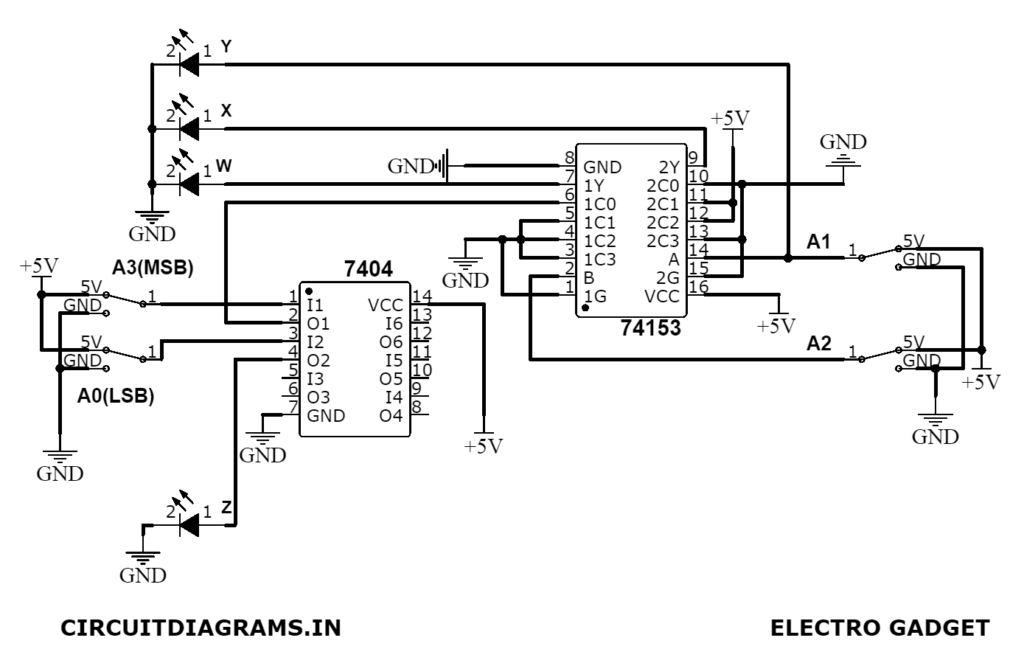
The objective of this 9’s complement using a dual multiplexer (IC-74153) is to fully understand and implement to generate 9’s complement.
The decimal number system comprises digits from 0-9 i.e., 0, 1, 2, 3, 4, 5, 6, 7, 8 and 9. The base or radix of the decimal number system is 10 because the total no of digits available in the decimal number system is 10. The 9’s complement of a number can be obtained by subtracting every digit of a number by 9.
Must Read 9’s Complement Using IC-7483
Project

Circuit Diagram
Components Required
- IC-74153 4:1 Dual Multiplexer
- IC-7404 NOT Gate
- Single Pole 2-Way Switch (x4)
- Green LED (x3)
- Red LED (x1)
- +5V Power Supply
- Wires
- Breadboard
About Parts of 9’s Complement Using Dual Multiplexer
IC-74153 (Dual 4:1 Multiplexer)
This IC chip contains two units of 4:1 MUXs with two common select inputs (S0, S1), but two separate active-low enable inputs. The block diagram of 74153 is shown in figure (2). Two select inputs S1 and S0 simultaneously control both sections of this MUX, but the two sections can be enabled or disabled by two independent Enable inputs, EN1 and EN2.
If S1=1 and S0=1. For example, the data through the input lines and 1I3 and 2I3 will be passed to the output 1Y and 2Y respectively provided both the strobe inputs are at logic 0. The data at the other inputs are irrelevant at this time. Now, if both the strobe inputs are at logic 1, then the data through the input lines are irrelevant at that time.
The function table for any section of this chip is shown in Table (2).
Truth Table for IC-74153
| EN | S1 | S0 | Y |
| 0 | 0 | 0 | I0 |
| 0 | 0 | 1 | I1 |
| 0 | 1 | 0 | I2 |
| 0 | 1 | 1 | I3 |
| 1 | X | X | 0 |
The two outputs 1Y and 2Y can be described by the following equation.

The expanded equation for the two outputs 1Y and 2Y are,

IC-7404 NOT Gate
The IC-7404 is a logic gate IC. It consists of six NOT gates. We know that the NOT gate is also called an inverter because it does complement any inputs. When applying zero or low signal to the input, it gives 1 or high signal as in the output and vice versa. The pin diagram of the IC-7404 is shown in figure (3).
Truth Table for IC-7404
| INPUT | OUTPUT |
| X | x̄ |
| 0 | 1 |
| 1 | 0 |
Working Principle of 9’s Complement Using Dual Multiplexer
Now, according to the given experimental assignment, we have to implement 4:1 MUX to design a circuit for getting 9’s complement. But we do not derive any direct formulation from a MUX for a complement. So, the only way to derive it is to value a detailed comparison from the Truth Table (1). The table is given below.
Truth Table for BCD and 9’s complement comparison
| A3 | A2 | A1 | A0 | W | X | Y | Z |
|---|---|---|---|---|---|---|---|
| 0 | 0 | 0 | 0 | 1 | 0 | 0 | 1 |
| 0 | 0 | 0 | 1 | 1 | 0 | 0 | 0 |
| 0 | 0 | 1 | 0 | 0 | 1 | 1 | 1 |
| 0 | 0 | 1 | 1 | 0 | 1 | 1 | 0 |
| 0 | 1 | 0 | 0 | 0 | 1 | 0 | 1 |
| 0 | 1 | 0 | 1 | 0 | 1 | 0 | 0 |
| 0 | 1 | 1 | 0 | 0 | 0 | 1 | 1 |
| 0 | 1 | 1 | 1 | 0 | 0 | 1 | 0 |
| 1 | 0 | 0 | 0 | 0 | 0 | 0 | 1 |
| 1 | 0 | 0 | 0 | 0 | 0 | 0 | 0 |
The working principle and circuit connection for this project are very simple. Now we can start the comparison from the truth table above. From the truth table, it is seen that Z=Ā and Y=A1. Now, for using the 4:1 MUX, we have to find the select inputs.
Now, from Table (1), we can see that A2 and A1 are both in a perfect sequence of [00, 01,10 & 11] thus for our case we have to choose A2 and A1 as the select inputs. S1 and S0 of IC-74153 as shown in figure (1). Then we get Y1=W and Y0=X. The output Y is obtained directly from A1 and the output Z is obtained using one inverter with A0 as the input.
Now, for the remaining two-bit W and X, we have to compare the inputs with outputs from Table (1).
| Input Lines | Combination | First half (4:1)MUX (IC-74153) | Second half (4:1)MUX (IC-74153) |
| I0 | A2A1=00 | Y1=W=A3 | Y0=X=0 |
| I1 | A2A1=01 | Y1=W=0 | Y0=X=1 |
| I2 | A2A1=10 | Y1=W=0 | Y0=X=1 |
| I3 | A2A1=11 | Y1=W=0 | Y0=X=0 |
The calculation for the Current Limiting Resistance
We are using Green LEDs. The standard forward voltage across Green LED = 2.0V and the forward current is about = 20 mA. We are using 5V as the supply voltage.
The current limiting resistor, Rs = (5-2)/(2×10-3) = 150Ω.
So, the necessary value of the current limiting resistor is 150Ω and we are using a 220Ω practical value.
Example of 9’s Complement Using Dual Multiplexer


