In this project, we are going to build a 3-phase inverter circuit and then we make a connection between a 3-phase motor and the inverter. We use an Arduino board to control it. Nowadays inverter is a very common appliance in our home. This device converts DC current into AC current. There are many types of inverters there.
This time we are going to build an Arduino-based 3-Phase Inverter circuit using BJT. In this project, we briefly explained the working principle of a 3-phase transformer. Then we show how to make this with single-phase transformers. We also show you the output wave generated by Arduino.
Industries and some home appliances require this type of inverter. So this project is going to be very interesting.
Must Read 35W 12V-220V Inverter Circuit
Project
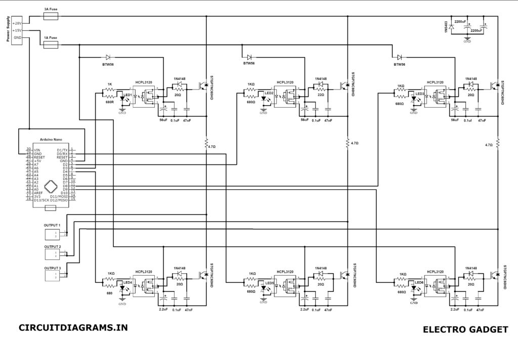
Circuit Diagram
Components Required
- Arduino Nano
- HCPL-3120 (x6)
- BTW56 Diode (x3)
- INF148 Diode (x6)
- IN5403 Diode
- STGP7NC60HD (x6)
- 56uF Capacitor (x3)
- 2.2uF Capacitor (x3)
- 47nF Capacitor (x6)
- 0.1uF Capacitor (x6)
- 4.7uF Capacitor (x3)
- LED (x6)
- 1Amp Fuse
- 3Amp Fuse
- 680 Ohm (x6)
- 20 Ohm (x6)
- 1K Resistor (x6)
- 2200uF (x2)
- Vero Board
- 28V Power Supply
- 15V Power Supply
About Parts
HCPL-3120
HCPL-3120 is a gate driver Optocoupler that contains a GaAsP LED. This LED has a power output stage with an integrated coupled circuit. It is best for IGBT and MOSFET driving motor control circuits. HCPL-3120 has a high operating voltage.
Working Principle of 3-Phase Inverter Circuit
Now I explain the connection and working of a 3-phase inverter with the 3-phase motor. The three-phase motor is connected here in a 3-phase star connection. When we power on the circuit, the display shows that it is in stop mode. Then we press a key and it switches to manual mode. In this condition, the motor turns on but very slowly. Now I increase the speed of the motor by the potentiometer. You can change it at various speeds by pressing another switch on the board. In this project, I set up 4 various speeds.
Now for reverse rotation of the motor, you have to press the first switch. If you add an ammeter, you can see the motor takes the same current in both directions. The motor also has various speeds in reverse mode.
Advantages of 3-Phase Inverter
- A 3-phase inverter circuit provides more efficient power than a single phase inverter.
- This is a very less cost project.
- There is no need to buy 3-phase transformer, which is very expensive.
- The circuit is very easy to design.
Arduino Code
Download this code from here.


Hi, what is the voltage of the capacitors and what is the power of the resistors? How is the output voltage adjusted? Is it possible to make a regulator for the output voltage from 60 to 100 volts?
I have a problem in Compile this program.
I get this error.
Compilation error: ‘OCR3A’ was not declared in this scope
Great project this is