In this tutorial, we will be going to learn how to build a simple 12V to 220V 35W inverter circuit. Inverters are often needed at places where load shedding is a common problem. There are two types of inverters, sine wave inverter which is very expensive, and modified inverters which price are inexpensive.
The modified inverter generates a square wave pulse in the output which is harmful to electronics equipment. For this reason, this type of inverter is not used in electronic equipment.
For this, a quite simple DC to AC voltage inverter circuit is designed with simple power transistors. This type of transistor uses as a switching device that transforms 12V DC voltage into single-phase AC (220V) voltage as an output.
Must Read Single Phase Full Bridge Inverter
Principle Behind 12V DC to 220V AC Inverter Circuit
The fundamental thought behind each inverter circuit is to deliver oscillations using the given DC and apply these oscillations across the primary coil of the transformer by enhancing the current. This output voltage is then stepped up to a higher voltage. The output voltage depends on the number of turns in the primary and secondary coils of the transformer.
In this article, we are going to make an inverter with transistors. This type of inverter produces a maximum of 35W in the load but this can also be modified by adding more MOSFETs. Those devices which do not require pure AC have used this type of inverter. Because this type of inverter does not produce pure sine wave signals.
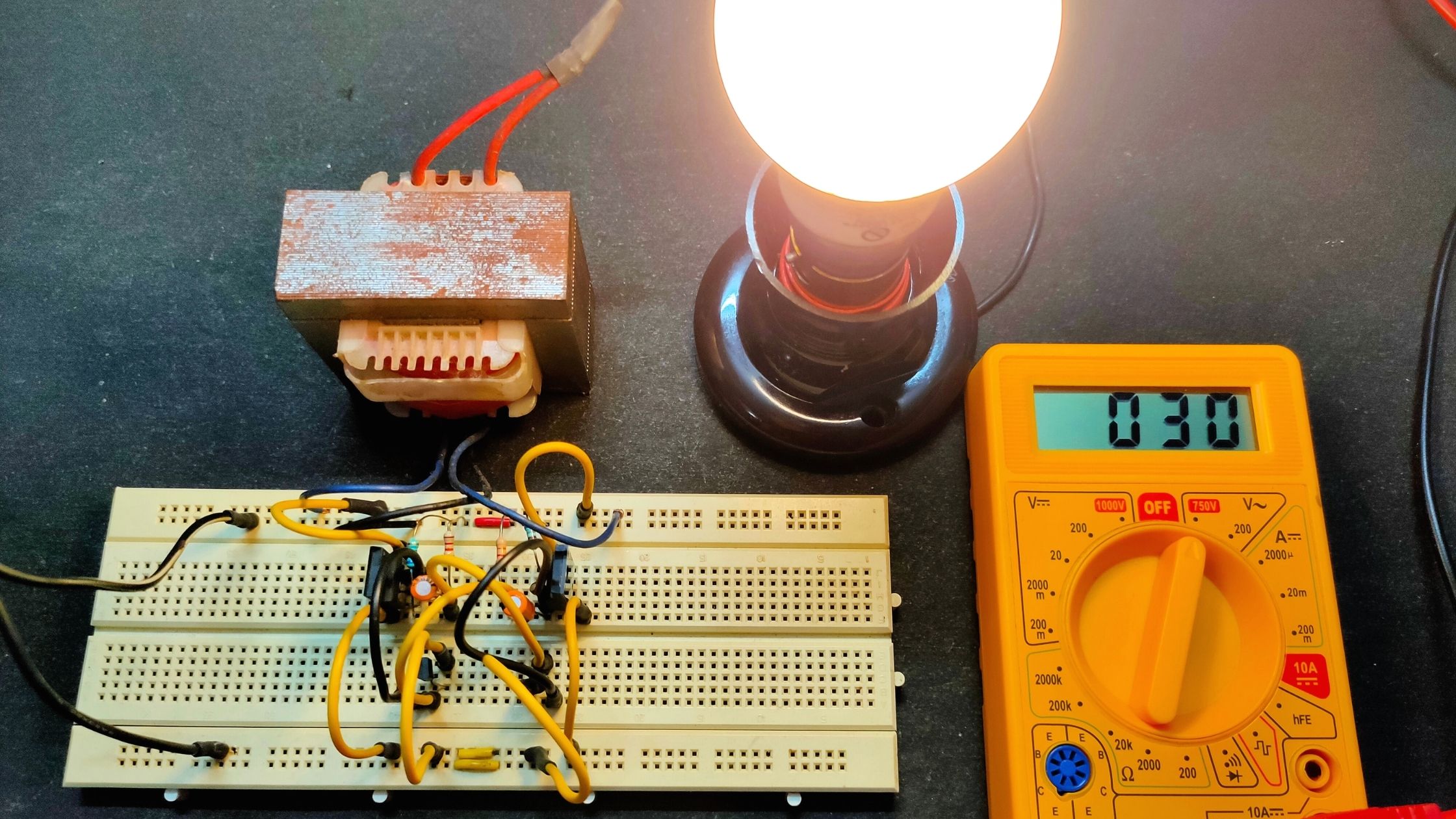
Project

Circuit Diagram

Components Required
- 12V-220V Center Tapped Step-Down Transformer
- 2N2222 Transistors (x2)
- MOSFET IRF630 (x2)
- (C1, C2) 2.2uF/60V Capacitors (x2)
- (R1, R4) Resistor 680Ω (x2)
- (R2, R3) Register 12KΩ (x2)
- 12V Battery
Circuit Connection
In order to connect all components, we started from the transformer. On the input of the transformer, one end of it is connected to the drain of the MOSFET Q1 and the other end is connected to the drain of the MOSFET Q2. The gate terminal of Q1 is connected to C1 and the C2 is connected to the gate terminal of Q2. The other end of C1 and C2 are connected to the R2 and R3 respectively. These are also connected to the centre of the transformer and the positive supply of the battery.
The source terminal of Q1 and Q2 are connected to the emitter of the transistor Q3 and Q4 respectively which are shorted to each other. The base terminal of Q3 and Q4 are connected to R3 and R2. The collector of the Q3 and Q4 connected to the R1 and R4 respectively. The R1 and R4 are also connected to the centre of the transformer and positive supply. Then we connect the 12V battery across the centre of the transformer (+V) and the emitter of Q3 and Q4 (-V). Now we complete the connection of this 35W inverter.
Working Principle of 12V DC to 220V AC inverter
In the working of this inverter circuit, we have to divide it into three parts. The first part is a 50Hz oscillator circuit which produces a 50Hz frequency in the AC signal. The second part is an amplifier circuit that amplifies the output AC. The last part is the transformer.
To create the oscillation we have to construct an astable multivibrator that produces a 50Hz frequency. In the circuit, you can see the resistors named R1, R2, R3, and R4, the capacitors C1, C2, and transistors Q3 and Q4 form the oscillator.
The transistors (Q3 and Q4) generate inverting square waves. In the circuit, R3, R4 and C2 are fixed. On depending the value of R1, R2 and C1, the frequency varies.
The formula of the frequency is: F = 1 / (1.38 × R2 × C1)
From the formula, we can see if we take a higher value of R2 and C1 the frequency will decrease and vice versa.
After this, the system enters the second stage which is the amplifier circuit. The amplifier amplifies the signal in the output of the oscillator. This amplification is made by the power MOSFETs Q1 and Q2.
Then it is connected to the step-down transformer with a centre tap connected to 12V DC. which converts it to 220 AC.
The ratio of the primary coil and secondary coil of the transformer must be 1:19 to convert 12V to 220V. This type supports the highest 35W.
In order to increase the capacity of the inverter, use a 24V battery and the number of MOSFETs should be increased.
Applications of 12V DC to 220V AC Inverter Circuit
- Many cars and vehicles use this type of inverter to charge 12V batteries.
- As a power supply of low power AC motor.
- Use in solar power systems.


Thanks sir what of how to make a full charge circuit using bc 547 transistor
Thanks how about how to make 300w to 500w inverter circuit diagram