In recent years, the need for efficient and real-time heat monitoring systems has become increasingly critical, particularly in areas related to environmental conditions. One such application is monitoring the heat index, which combines air temperature and relative humidity to estimate how hot it feels. Accurate and timely measurement of the heat index is essential for various sectors, including agriculture, health care, and meteorology, to ensure safety and optimal performance.
This project presents an “Arduino Real-Time Heat Index System” using the DHT11 sensor and an I2C LCD display. The DHT11 sensor is a low-cost digital sensor that measures temperature and humidity, making it ideal for calculating the heat index. By integrating this sensor with an Arduino microcontroller and an I2C LCD display, we can create a simple yet effective system to continuously monitor and display the heat index in real-time.
The Arduino platform is chosen for its versatility and ease of use, making it accessible even for beginners. The I2C LCD display is used to provide a clear and concise output of the heat index, ensuring that the information is readily available and easy to interpret. This project not only demonstrates the practical application of these components but also serves as an educational tool for those learners interested in learning more about Arduino-based embedded systems and environmental monitoring system.
Must Read Weather Monitoring Device Using Arduino
Circuit Diagram

Components Required
- Arduino Board (Arduino Nano or Uno)
- DHT11 Temperature and Humidity Sensor
- I2C LCD Display
- Breadboard
- Jumper Wires
- USB Cable for Arduino
Understanding the Components
DHT11 Sensor: This is a basic, low-cost digital sensor used for measuring temperature and humidity. It provides a calibrated digital output and is simple to interface with any microcontroller.
I2C LCD Display: An LCD screen with an I2C interface is used to display the heat index. The I2C interface simplifies the wiring, reducing the number of pins required to connect the LCD to the Arduino.
Arduino Nano: This open-source platform consists of both hardware and software. It’s perfect for beginners due to its simplicity and large community support.
Connection of the Components
Wiring the DHT11 Sensor:
- Connect the VCC pin of the DHT11 to the 5V pin on the Arduino.
- Connect the GND pin to the GND on the Arduino.
- Connect the DATA pin to digital pin 2 on the Arduino.
Wiring the I2C LCD Display:
- Connect the VCC and GND pins of the I2C module to the 5V and GND pins on the Arduino, respectively.
- Connect the SDA (data) pin to the A4 pin on the Arduino.
- Connect the SCL (clock) pin to the A5 pin on the Arduino.
Prepare & Upload Code
- Open the Arduino IDE.
- Go to Sketch > Include Library > Add .ZIP Library.
- Install both the DHT and Adafruit sensor library.
- Install the LiquidCrystal I2C library.
- Connect your Arduino to your computer using a USB cable.
- Select the correct board and port in the Arduino IDE under Tools.
- Click the upload button to transfer the code to your Arduino.
1 2 3 4 5 6 7 8 9 10 11 12 13 14 15 16 17 18 19 20 21 22 23 24 25 26 27 28 29 30 31 32 33 34 35 36 37 38 39 40 41 42 43 44 45 46 47 48 49 50 51 52 53 54 55 56 57 58 59 60 61 | #include <Wire.h> #include <LiquidCrystal_I2C.h> #include <DHT.h> #define DHTPIN 2 // Pin which is connected to the DHT sensor #define DHTTYPE DHT11 // DHT 11 DHT dht(DHTPIN, DHTTYPE); LiquidCrystal_I2C lcd(0x27, 16, 2); // Set the LCD address to 0x27 for a 16 chars and 2 line display unsigned long previousMillis = 0; // Stores last time the screen was updated const long interval = 5000; // Interval at which to switch screens (milliseconds) bool showHeatIndex = false; void setup() { lcd.init(); lcd.backlight(); lcd.setCursor(0, 0); lcd.print("Electro Gadget"); delay(2000); lcd.clear(); dht.begin(); } void loop() { unsigned long currentMillis = millis(); // Reading temperature and humidity float h = dht.readHumidity(); float t = dht.readTemperature(); // Check if any reads failed and exit early (to try again). if (isnan(h) || isnan(t)) { lcd.setCursor(0, 0); lcd.print("Failed to read"); lcd.setCursor(0, 1); lcd.print("from DHT sensor"); return; } // Compute heat index in Celsius (isFahrenheit = false) float hic = dht.computeHeatIndex(t, h, false); if (currentMillis - previousMillis >= interval) { previousMillis = currentMillis; showHeatIndex = !showHeatIndex; lcd.clear(); } if (showHeatIndex) { // Display heat index lcd.setCursor(0, 0); lcd.print("Heat Index:"); lcd.setCursor(0, 1); lcd.print(hic); lcd.print((char)223); // Degree symbol lcd.print("C"); } else { // Display temperature and humidity lcd.setCursor(0, 0); lcd.print("Temp: "); lcd.print(t); lcd.print((char)223); // Degree symbol lcd.print("C"); lcd.setCursor(0, 1); lcd.print("Humidity: "); lcd.print(h); lcd.print("%"); } } |
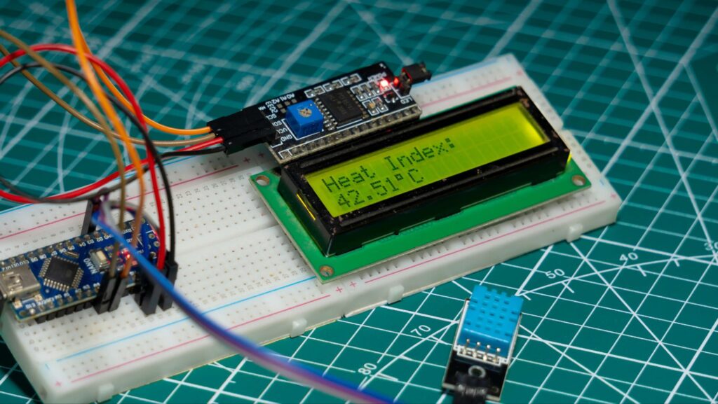
Testing the Real-Time Heat Index System
Once the code is uploaded, your LCD display should start showing the current temperature and humidity along with the calculated real-time heat index. The DHT11 sensor will continuously provide the Arduino with temperature and humidity data, and the heat index will be updated in real-time.
Troubleshooting of Arduino Real-Time Heat Index System
When building an Arduino real-time heat index system using a DHT11 sensor and an I2C LCD display, you might encounter some issues. Here are common problems and their solutions:
1. No Display on LCD
Problem: The LCD does not show any information.
Solutions:
- Check Connections: Ensure that all wires are correctly connected to the Arduino and the LCD.
- Power Supply: Verify that the LCD is receiving power from the Arduino.
- I2C Address: Make sure the I2C address in your code matches the address of your LCD module. You can use an I2C scanner sketch to find the correct address.
- Contrast Adjustment: Adjust the potentiometer on the I2C module to change the contrast of the LCD.
2. Incorrect Temperature or Humidity Readings
Problem: The DHT11 sensor is providing incorrect or erratic readings.
Solutions:
- Sensor Placement: Ensure the sensor is placed in a location free from direct sunlight or heat sources that can skew readings.
- Stable Environment: Wait a few minutes after powering up the system for the sensor to stabilize.
- Code Issues: Verify the code for the correct implementation of the DHT11 library and sensor pin configuration.
3. Error Messages in Arduino IDE
Problem: The Arduino IDE displays error messages during compilation or uploading.
Solutions:
- Library Installation: Ensure all necessary libraries (DHT, LiquidCrystal I2C) are installed correctly.
- Board Selection: Confirm that the correct Arduino board is selected in the Tools menu.
- Port Selection: Verify that the correct COM port is selected for your Arduino.
4. DHT11 Sensor Not Responding
Problem: The sensor does not provide any data.
Solutions:
- Wiring: Double-check the connections, ensuring the data pin is connected to the correct digital pin on the Arduino.
- Pull-up Resistor: Some setups may require a pull-up resistor (10kΩ) between the VCC and data pin of the DHT11.
- Sensor Fault: Test the sensor with a simple sketch to ensure it is working correctly.
5. LCD Display Shows Garbage or Incorrect Characters
Problem: The LCD displays random characters or gibberish.
Solutions:
- I2C Address: Verify and correct the I2C address in your code.
- Connection Stability: Ensure all I2C connections are secure.
- Code Errors: Ensure that the LiquidCrystal I2C library is correctly implemented in your code.
6. Heat Index Not Calculating Correctly
Problem: The heat index value displayed is incorrect or not updated.
Solutions:
- Sensor Readings: Ensure the temperature and humidity readings are accurate.
- Heat Index Formula: Verify that the formula used in the code to calculate the heat index is correct.
- Data Refresh Rate: Check the delay in your loop to ensure the sensor has enough time to read and update data correctly.
Applications of an Arduino Real-Time Heat Index System
A real-time heat index monitoring system can be extremely useful in various fields. Here are some key applications:
1. Agriculture
- Crop Management: Prevents heat stress in crops.
- Livestock Safety: Protects animals from extreme heat.
2. Healthcare
- Patient Care: Manages indoor climates for sensitive patients.
- Elderly Care: Ensures safe conditions for the elderly.
3. Home Automation
- Climate Control: Integrates with HVAC systems.
- Safety Alerts: Triggers alarms for high heat index levels.
4. Industrial Applications
- Workplace Safety: Ensures safe working environments.
- Equipment Protection: Prevents overheating of sensitive equipment.
5. Urban Planning
- Smart Cities: Manages urban microclimates.
- Public Spaces: Ensures comfort in parks and playgrounds.
6. Education
- STEM Learning: Teaches students about environmental monitoring.
- DIY Projects: Encourages hobbyist exploration of electronics.
Conclusion
Building an Arduino-based real-time heat index system is a fantastic way to get started with electronics and programming. It’s a practical project that provides useful information and can be expanded upon in numerous ways, such as adding data logging capabilities or integrating with other sensors. This project not only enhances your understanding of Arduino and its components but also underscores the importance of environmental monitoring in everyday life.