A password based door lock system using an 8051 microcontroller is a project where you can secure your doors with a password. Traditional lock systems which are using mechanical locks are replaced by modern technologies. These techniques are electrical and highly intelligent. These systems are also very efficient than older locks. We can use the door unlocking system as an automated room appliance. Like we open the door and the light and fan of the room turn on.
In this project, we going to build a password-based door lock system using an AT89C51 microcontroller. This project also provides the control to actuate the load. This system is very easy to use like only with a keypad you can operate it.
In the present day, this system is used to protect secure areas. Where those people can only enter who have passwords or permission to enter. After anyone enters the room the doors are locked again. When any other arrives, the system asks for a password. If this person enters the wrong password the doors remain closed.
Must Read Celsius Scale Digital Thermometer Using AT89C51 Microcontroller
Principle Behind Door Lock System
This project is based on an 8051 microcontroller. The 4×4 matrix keypad is used here to enter the password. The system compares this password with the predefined password.
When two passwords are matched, the system opens the door by rotating the motor. It also displays the status of the doot on the LCD. If the password does not match the door remains closed and it displays “PWD is wrong” on LCD.
Project
Door Lock System Algorithm
- At first, we take PORT1 to LCD data pins and P3.0 and P3.2 to control pins (Rs and E). Then declare PORT2 to the keypad. We connect the motor driver to P0.0 and P0.1.
- Then the LCD displays the “enter the password” message.
- After entering the password by the user, it starts to read the five-digit password.
- The microcontroller compares the entered password and the predefined password.
- If the password is matched, then make P0.0 HIGH and P0.1 LOW. So the door opens. During this, the LCD displays “Door opening”.
- After 10 seconds the microcontroller makes P0.0 LOW and P0.1 HIGH. So the door again locked.
- If the entered password does not match, the LCD displays “Wrong Password”. So the door remains locked.
- After a delay, it displays again to enter the password.
Circuit Diagram

Components Required
Hardware Requirements
- 8051 Microcontroller (AT89C51)
- 8051 Development Board
- Programmer (8051)
- 4×4 Matrix Keypad
- 16×2 LCD
- 7805 Regulator IC
- 100uF/25V Capacitor
- 0.1uF Ceramic Capacitor
- L293D Motor Driver IC
- DC Motor
- 10KΩ Potentiometer
- Connecting Wires
- 9V-12V Power Supply
Software Requirements
- Keil µVision IDE
- Willar Programmer
Additional Components
If 8051 Development Board is not used, then the following components are needed.
- 11.0592 MHz Quartz Crystal
- 2 x 33pF Ceramic Capacitors
- 2 x 10 KΩ Resistor (1/4 Watt)
- 10 µF Capacitor (Polarized)
- Push Button
- 2 x 1 KΩ Resistors (for pull-up)
8051 Microcontroller Connection Section
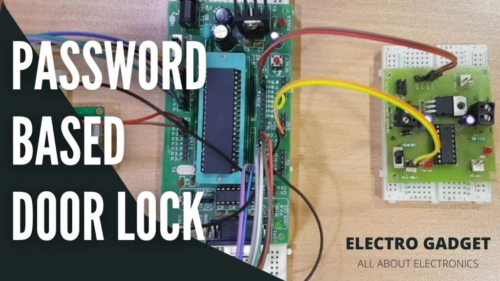
To build the password-based door lock system using the 8051 microcontroller circuit, we have five main components. Those are an AT89C52 Microcontroller, an L293D Motor driver, a DC motor, a 4×4 Matrix keypad, and last thing is a 16×2 LCD. In this project, we use the AT89C52 Microcontroller as an 8-bit controller. This controller works on +5V DC. We use 7805 IC to provide this 5V to the microcontroller. You can use a 9V/12V battery or 12V,1A adapter as a power supply for this circuit.
Reset Section
The reset pin of the microcontroller is kept active until the specified range of the power supply is changed. In other words to ensure the voltage does not fall below 1.2V. The minimum oscillation must be maintained and this is the second criterion to remain the reset pin activated. The reset pulls width is 100ms. For these two criteria, we select a 10K resistor and 10uF electrolytic capacitor to maintain RC >= 100ms.
Oscillator Section
In this project, we use an 11.0592 MHz crystal oscillator to provide the external clock signal to the microcontroller. For smooth operation, we connect two ceramic capacitors of 33pF. The crystal connects between pins 18 and 19 of the microcontroller.
Connecting LCD, Keypad, And Motor Driver IC
After connecting the crystal, we take a 10K potentiometer and connect it with the LCD’s contrast pin ( no. 3). RS, RW, and E of the LCD are connected to P3.0, GND, and P3.2 pins respectively. The data lines of the LCD are connected to P1.
Pins P2.0 and P2.3 are connected to the four ROW pins of the keypad. The COLUMN pins are connected to pins P2.4 and P2.7. The input pins ( 1A and 2A) of the L293D motor driver are connected to P0.0 and P0.1. We connect the motor between output pins (1Y and 2Y) of L293D.
Compilation of Microcontroller Code
Hence we complete connecting all the parts of this circuit. Now we have to compile with the code. Keli uVision software is used here to write the program in C language.
Some basic steps are to be followed like creating a new project and selecting the required microcontroller. After writing the code we save the file with an extension of c. Then add it to the source file under the target folder. Now press F7 to compile the code.
After compiling the code you can see a hex file is created. Then we use Easy EDA software to draw the circuit and design the PCB from it.
Working Principle of Door Lock System
At first, when we power on the circuit, the microcontroller sends commands to the LCD. The LCD displays “enter password”. Now we have to enter the password using the keypad. Once we entered the password, it displays 5 stars on LCD. That is the indication of the controller read the password successfully.
Now the controller compares the predefined password and the recently entered password. If those passwords are matched, then the microcontroller makes P0.0 HIGH and P0.1 LOW. It gives the motor driver input signals for forwarding motion to the motor.
As a result, the door motor rotates forward direction and the door opens. After 10 seconds the microcontroller makes P0.0 LOW and P0.1 HIGH. Now motor driver gets an input to reverse the motion. So the door motor rotates reverse and the door again locked.
Now if the password does not match, what will happen? The answer is microcontroller maintains both P0.0 and P0.1 LOW. So the door motor does not get any motion and the door remains locked.
Application of Door Lock System
- This circuit can be used as a door lock like key locks.
- It can be used in highly secure places to secure important documents.
- With some modifications, this project can be used as a password-based home appliances system.
Advantages of Door Lock System
- This project is very simple.
- The components are very common.
- Less power consumption.
- It is a very simple but good security system.
Limitations of Door Lock System
- This circuit can not be used remotely.
- By any chance you forget the password, the door can not be opened.
Microcontroller Code
1 2 3 4 5 6 7 8 9 10 11 12 13 14 15 16 17 18 19 20 21 22 23 24 25 26 27 28 29 30 31 32 33 34 35 36 37 38 39 40 41 42 43 44 45 46 47 48 49 50 51 52 53 54 55 56 57 58 59 60 61 62 63 64 65 66 67 68 69 70 71 72 73 74 75 76 77 78 79 80 81 82 83 84 85 86 87 88 89 90 91 92 93 94 95 96 97 98 99 100 101 102 103 104 105 | #include<reg52.h> sbit r0=P2^0; sbit r1=P2^1; sbit r2=P2^2; sbit r3=P2^3; sbit c0=P2^5; sbit c1=P2^6; sbit c2=P2^7; sbit en=P3^6; sbit rs=P3^5; sbit rw=P3^7; sbit lock=P3^0; char t1[]="Enter PIN:"; char t2[]="Access Granted"; char t3[]="Access Denied"; char pin[]="1234"; char pinEntered[4]; unsigned int m = 0; unsigned int flag = 0; void delay(unsigned int no) { unsigned int i,j; for(j=0;j<=no;j++) for(i=0;i<=10;i++); } void lcdcmd(unsigned int command){ P1=command; rw=0; rs=0; en=0; delay(1000); en=1; delay(1000); en=0; } void lcddata(char data1) { P1=data1; rw=0; rs=1; en=0; delay(1000); en=1; delay(1000); en=0; } void lcdint(){ lcdcmd(0x30); delay(1000); lcdcmd(0x30); delay(1000); lcdcmd(0x30); delay(1000); lcdcmd(0x30); delay(1000); lcdcmd(0x30); delay(1000); lcdcmd(0x38); delay(1000); lcdcmd(0x01); delay(1000); lcdcmd(0x0F); delay(1000); lcdcmd(0x80); delay(1000); } char keypad() { char c='a'; while(c!='s'){ r0=0;r1=1;r2=1;r3=1; if(c0==0){lcddata('1');P0=0xF0;delay(10000);c='s';return '1';} if(c1==0){lcddata('2');P0=0xF0;delay(10000);c='s';return '2';} if(c2==0){lcddata('3');P0=0xF0;delay(10000);c='s';return '3';} r0=1;r1=0;r2=1;r3=1; if(c0==0){lcddata('4');P0=0xF0;delay(10000);c='s';return '4';} if(c1==0){lcddata('5');P0=0xF0;delay(10000);c='s';return '5';} if(c2==0){lcddata('6');P0=0xF0;delay(10000);c='s';return '6';} r0=1;r1=1;r2=0;r3=1; if(c0==0){lcddata('7');P0=0xF0;delay(10000);c='s';return '7';} if(c1==0){lcddata('8');P0=0xF0;delay(10000);c='s';return '8';} if(c2==0){lcddata('9');P0=0xF0;delay(10000);c='s';return '9';} r0=1;r1=1;r2=1;r3=0; //if(c0==0){lcddata('*');P0=0xF0;delay(10000);c='s';return '1';} if(c1==0){lcddata('0');P0=0xF0;delay(10000);c='s';return '0';} // if(c2==0){lcddata('#');P0=0xF0;delay(10000);c='s';return '1';} } } void main() { unsigned int i=0; P1=0x00; P2=0xF0; P3=0x00; lcdint(); while(1){ i=0; while(t1[i]!='\0') { lcddata(t1[i]); i++; } lock=0; lcdcmd(0xC0); for(i=0;i<=3;i++) pinEntered[i] =keypad(); i=0; lcdcmd(0x01); if(pinEntered[0]==pin[0]) { i++; if(pinEntered[1]==pin[1]) { if(pinEntered[2]==pin[2]) { if(pinEntered[3]==pin[3]) { lock=1; i=0; while(t2[i]!='\0') { lcddata(t2[i]); i++; }i=0; } } } }else{ i=0; while(t3[i]!='\0') { lcddata(t3[i]); i++; } i=0; } if(i!=0) { i=0; while(t3[i]!='\0') { lcddata(t3[i]); i++; } } delay(1000000); lcdcmd(0x01); lcdcmd(0x80); i=0; } } |