Previously, we have built some camera-based IoT projects using the ESP32-CAM Development Board. Those are very effective projects for home automations. So we thought to innovate some new projects using these ideas for the security system.
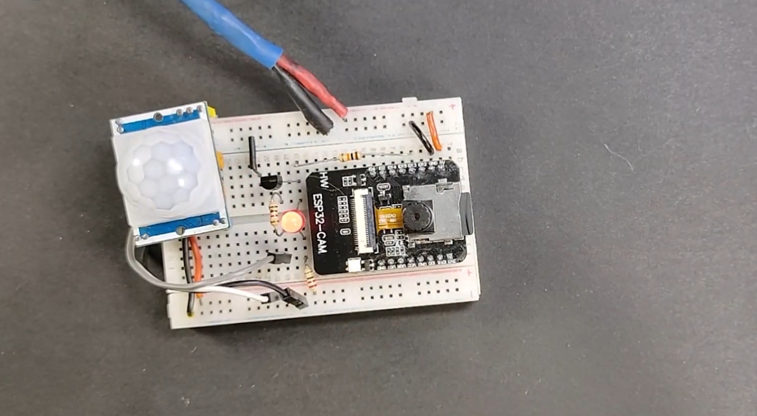
In this project, we’re going to make a Motion Sensing Photo Capturing Device using the ESP32-CAM module. For that, we use a PIR motion sensor for detection. When the PIR sensor detects any motion near the device, it will automatically capture a photo, and save it on the microSD card.
Project

Circuit Diagram

Components Required
- ESP32-CAM WiFi Camera Module
- FTDI Programming Module
- PIR Motion Sensor
- 2N3904 Transistor
- 1K Resistor
- Connection Wire
- Breadboard
- 5V Hi-Link Converter
ESP32-CAM Module Specifications
The ESP32-CAM is based on the ESP32-S module. It has the same features.
- 802.11b/g/n Wi-Fi
- Bluetooth 4.2 with BLE
- UART, SPI, I2C, and PWM interfaces
- Clock speeds up to 160 MHz
- Computing power up to 600 DMIPS
- 520KB SRAM + 4 MB PSRAM
- Supports WiFi Image Upload
- Multiple sleep modes
- Firmware Over the Air (FOTA) upgrades possible
- 9 GPIO ports
- Built-in Flash LED
Camera Specifications for Motion Sensing Photo Capturing
The ESP32-CAM has an inbuilt OV2640 camera module. The device also supports OV7670 cameras.
- 2 megapixel camera sensor
- Array size UXGA 1622×1200
- Output formats include YUV422, YUV420, RGB565, RGB555 and 8-bit compressed data
- Image transfer rate of 15 to 60 fps
Programming ESP32-CAM Camera Module
First, to program the ESP32-CAM module, first, connect the module to a USB-to-Serial FTDI converter as shown in the schematic below.

| ESP32-CAM | FTDI Module |
|---|---|
| U0R | TX |
| U0T | RX |
| GPIO0 | GND |
| +5V | +5V |
| GND | GND |

To program and be ready to upload the code to the ESP32-CAM module, connect GPIO pin 0 to the ground as mentioned above schematic. Also, need to press the reset button to set it to flash mode before uploading the code.
Before uploading the code, make sure that you have the “https://raw.githubusercontent.com/espressif/arduino-esp32/gh-pages/package_esp32_index.json” link pasted into the preferences tab of the Arduino IDE. This link provides you access to example codes, libraries you need, etc.
Working Principle of Motion Sensing Photo Capturing Device
Now let’s talk about the working principle of this simple motion sensing photo capturing device.
At the stand-by situation, the ESP32-CAM module is in deep sleep mode with external wake-up enabled.
When any motion is detected in front of the camera viewing area, the PIR motion sensor sends an Analog signal to wake up the ESP32-CAM.
At the same time, ESP32-CAM takes a photo of the moving object and saves it on the microSD card.
Thereafter, again it turns back to deep sleep mode until another signal from the PIR motion sensor is received.
ESP32-CAM Code
To develop this code, all credit goes to Rui Santos.
#include "esp_camera.h"
#include "Arduino.h"
#include "FS.h"                // SD Card ESP32
#include "SD_MMC.h"            // SD Card ESP32
#include "soc/soc.h"           // Disable brownour problems
#include "soc/rtc_cntl_reg.h"  // Disable brownour problems
#include "driver/rtc_io.h"
#include <EEPROM.h>            // read and write from flash memory
// define the number of bytes you want to access
#define EEPROM_SIZE 1

RTC_DATA_ATTR int bootCount = 0;
// Pin definition for CAMERA_MODEL_AI_THINKER
#define PWDN_GPIO_NUM     32
#define RESET_GPIO_NUM    -1
#define XCLK_GPIO_NUM      0
#define SIOD_GPIO_NUM     26
#define SIOC_GPIO_NUM     27
#define Y9_GPIO_NUM       35
#define Y8_GPIO_NUM       34
#define Y7_GPIO_NUM       39
#define Y6_GPIO_NUM       36
#define Y5_GPIO_NUM       21
#define Y4_GPIO_NUM       19
#define Y3_GPIO_NUM       18
#define Y2_GPIO_NUM        5
#define VSYNC_GPIO_NUM    25
#define HREF_GPIO_NUM     23
#define PCLK_GPIO_NUM     22

int pictureNumber = 0;

void setup() {
  WRITE_PERI_REG(RTC_CNTL_BROWN_OUT_REG, 0); //disable brownout detector
  Serial.begin(115200);

  Serial.setDebugOutput(true);

  camera_config_t config;
  config.ledc_channel = LEDC_CHANNEL_0;
  config.ledc_timer = LEDC_TIMER_0;
  config.pin_d0 = Y2_GPIO_NUM;
  config.pin_d1 = Y3_GPIO_NUM;
  config.pin_d2 = Y4_GPIO_NUM;
  config.pin_d3 = Y5_GPIO_NUM;
  config.pin_d4 = Y6_GPIO_NUM;
  config.pin_d5 = Y7_GPIO_NUM;
  config.pin_d6 = Y8_GPIO_NUM;
  config.pin_d7 = Y9_GPIO_NUM;
  config.pin_xclk = XCLK_GPIO_NUM;
  config.pin_pclk = PCLK_GPIO_NUM;
  config.pin_vsync = VSYNC_GPIO_NUM;
  config.pin_href = HREF_GPIO_NUM;
  config.pin_sscb_sda = SIOD_GPIO_NUM;
  config.pin_sscb_scl = SIOC_GPIO_NUM;
  config.pin_pwdn = PWDN_GPIO_NUM;
  config.pin_reset = RESET_GPIO_NUM;
  config.xclk_freq_hz = 20000000;
  config.pixel_format = PIXFORMAT_JPEG;

  pinMode(4, INPUT);
  digitalWrite(4, LOW);
  rtc_gpio_hold_dis(GPIO_NUM_4);

  if(psramFound()){
    config.frame_size = FRAMESIZE_UXGA; // FRAMESIZE_ + QVGA|CIF|VGA|SVGA|XGA|SXGA|UXGA
    config.jpeg_quality = 10;
    config.fb_count = 2;
  } else {
    config.frame_size = FRAMESIZE_SVGA;
    config.jpeg_quality = 12;
    config.fb_count = 1;
  }

  // Init Camera
  esp_err_t err = esp_camera_init(&config);
  if (err != ESP_OK) {
    Serial.printf("Camera init failed with error 0x%x", err);
    return;
  }

  Serial.println("Starting SD Card");

  delay(500);
  if(!SD_MMC.begin()){
    Serial.println("SD Card Mount Failed");
    //return;
  }

  uint8_t cardType = SD_MMC.cardType();
  if(cardType == CARD_NONE){
    Serial.println("No SD Card attached");
    return;
  }

  camera_fb_t * fb = NULL;

  // Take Picture with Camera
  fb = esp_camera_fb_get();
  if(!fb) {
    Serial.println("Camera capture failed");
    return;
  }
  // initialize EEPROM with predefined size
  EEPROM.begin(EEPROM_SIZE);
  pictureNumber = EEPROM.read(0) + 1;

  // Path where new picture will be saved in SD Card
  String path = "/picture" + String(pictureNumber) +".jpg";

  fs::FS &fs = SD_MMC;
  Serial.printf("Picture file name: %s\n", path.c_str());

  File file = fs.open(path.c_str(), FILE_WRITE);
  if(!file){
    Serial.println("Failed to open file in writing mode");
  }
  else {
    file.write(fb->buf, fb->len); // payload (image), payload length
    Serial.printf("Saved file to path: %s\n", path.c_str());
    EEPROM.write(0, pictureNumber);
    EEPROM.commit();
  }
  file.close();
  esp_camera_fb_return(fb);

  delay(1000);

  // Turns off the ESP32-CAM white on-board LED (flash) connected to GPIO 4
  pinMode(4, OUTPUT);
  digitalWrite(4, LOW);
  rtc_gpio_hold_en(GPIO_NUM_4);
  esp_sleep_enable_ext0_wakeup(GPIO_NUM_13, 0);

  Serial.println("Going to sleep now");
  delay(1000);
  esp_deep_sleep_start();
  Serial.println("This will never be printed");
}

void loop() {

}Applications of Motion Sensing Photo Capturing Device
- Usually used in home security systems.
- Large uses in local shops, malls, banks, companies, etc.