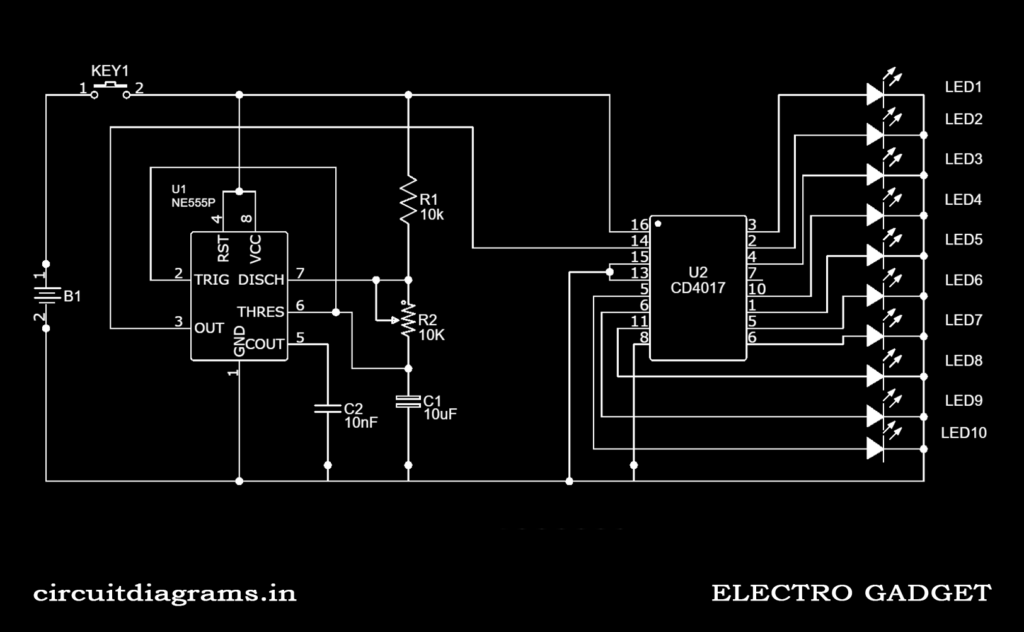
In this tutorial, a simple led chaser circuit can be made using 555 timers and CD4017 IC with some simple steps. This circuit can be used in blinking lighting, chaser lighting, and many decorative items. By modifying the circuit with relays you can use this to control lights working on AC electric units.
Must Read WS2812B Addressable LED using Arduino
Project
Circuit Diagram
Components Required
- CD4017 Counter
- 555 Timer
- LEDs
- 10 KΩ Resistor
- 10 KΩ Variable Resistor
- 10 μF/25V Capacitor
- 10 nF Capacitor
- 9V Battery
- Breadboard
Circuit Connection
In the above-led chaser circuit, you can see that the IC 555 timer is used as an astable multivibrator and its output pin 3 is connected to the clock input of the 4017 IC.
The output frequency of the 555 timers is determined by the resistors R1 (10 KΩ), R2 (10 KΩ pot), and capacitor C1 (10 uF/25V).
VCC pin 8 and ground pin 1 are respectively connected to the power supply.
Control Voltage pin 5 is not used, so to avoid high-frequency noise we are connecting a capacitor C2 (10 nF) to the ground.
Similarly, VDD pin 16 and VSS pin 8 of the CD4017 IC is connected directly to the power supply.
Clock enable pin 13 is an active low input, so it is connected to the ground. Clock input pin 14 is connected to the output of 555 timer pin 3. Each decoded output pin (Q0 – Q11) is connected to LEDs.
Working Principle of Led Chaser
As I explained above led the chaser circuit, 555 timers are used as an astable multivibrator. So the 555 timer IC will produce square wave output that acts as a clock pulse for the CD4017 IC.
This pulsating output from the timer IC is directly connected to the clock input pin 14 of 4017 IC. This counter IC has 10 output pins.
Each time when the clock input detects a voltage, it turns off the present output and turns on the next sequential output. For this reason, we can see that the LEDs are chasing each other.
The output frequency of the 555 timer IC is given by the following equation.
Output Frequency = 1.44/((R1 + 2R2) * C1)
We can easily change the output frequency of the LED chaser circuit by altering the variable resistance R2. It is used to control the LEDs chasing speed.

