In this article, we will talk about ACS712 Current Sensor and how a “Hall Effect” based current sensor works and how to interface it with Arduino.
A current sensor is a must in power calculation and management applications. It measures the current that flows through a device or a circuit and gives us the appropriate signal that is proportional to the current measured. Usually, the output signal is an Analog voltage.
About ACS712 Current Sensor
The ACS712 current sensor is a device based on Allegro MicroSystems which can be used to measure both AC and DC currents precisely. This sensor is made with Hall Effect and the IC got an integrated Hall Effect mechanism.
The output of the ACS712 current sensor produces an Analog voltage proportional to AC or DC currents (whichever is sensed).
ACS712 Current Sensor Module
One of the variants of the ACS712 IC (5A, 20A or 30A) is used in this project, several manufacturers developed ASC712 current sensor module boards that are very easy to interface with Arduino.
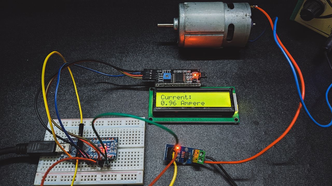
As we can see, it is a simple board with only a few components including the ASC712 IC and some passive components and connectors.
This specific board consists of ASC712 ELC-30 i.e., the effective range of this board is +/- 30A. As we can see the components and the pins on the board in the image.
Interfacing ASC712 Current Sensor With Arduino
Measuring voltages (DC Voltages) using Arduino is a very easy task. If you want to measure less than or equal to 5V, then you have to directly measure using the Arduino Analog pins. If you are required to measure more than 5V, then you have to use a simple voltage divider network or a voltage sensor module.
When it’s time to measure current, Arduino (or any other microcontroller) requires the assistance of a dedicated current sensor. So, Interfacing an ACS712 current sensor with Arduino helps us measure the current with the help of Arduino.
ASC712 is used to measure either AC or DC currents, and Arduino can be used to measure the same.
Project

Circuit Diagram

Components Required
- Arduino UNO
- ASC712 Current Sensor Module
- 16×2 LCD Display
- I2C Display Module
- 10KΩ Potentiometer
- 330Ω Resistor
- Connecting Wires
- Load
- 5V Power Supply
Working Principle of ACS712 Current Sensor
As we discussed earlier, the ASC712 is made with Hall Effect. It is a copper strip that connects the IP+ and IP- pins internally. When some current goes through this copper conductor, a magnetic field is created that is sensed by the Hall Effect sensor. Now the Hall Effect sensor’s part is to convert this magnetic field into appropriate voltage. The input and the output are completely isolated in this process.
Arduino Code
#include <LiquidCrystal_I2C.h>
#include <Wire.h>
LiquidCrystal_I2C lcd(0x27,20,4);
void setup() {
  Serial.begin(9600);
  lcd.init();
  lcd.backlight();
}
void loop() {
float value=0.0;
long int sum_of_reads = 0;
for (int x = 0; x < 200; x++){
  sum_of_reads += analogRead(A0);
  delay(3);
}
value = sum_of_reads/200;
value = (2.5 - (value * (5.0 / 1024.0)) )/0.066;
value = abs(value);
value -= 0.15;
Serial.println(abs(value));
lcd.clear();
lcd.setCursor(0, 0);
lcd.print("Current: ");
lcd.setCursor(0, 1);
lcd.print(abs(value));
lcd.print(" A");
delay(100);
}


