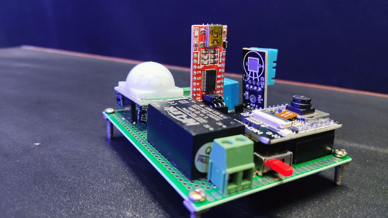
Hi folks! today I am here to discuss such an interesting topic how we could interface different sensors or modules in a single microcontroller board. In my case, I choose the ESP8266 NodeMCU board as it is easy to available and the cheapest IoT board. Also, I will integrate these sensors with my smartphone via the new Blynk software.
This system includes parameters like temperature and humidity monitoring, GAS level monitoring, security alert system, and water level monitoring. And to do those, we need a DHT11 sensor which is able to capture the surrounding’s temperature and humidity level precisely. MQ2 gas sensor can sense the surrounding gas level. The ultrasonic sensor can measure the water level in a particular tank, and the PIR sensor will work as a security alert system.
To display those measured data, I will also add an LCD display to the system to display the real-time activity of the system on the smartphone as well as on the LCD display. New Blynk 2.0 setup is a little tricky, so we also covered it in this project step by step.
Project

Circuit Diagram

Components Required
- ESP8266 NodeMCU
- HC-SR04 Ultrasonic Sensor
- DHT11 Humidity & Temperature Sensor
- PIR Motion Sensor
- MQ-2 Gas Sensor
- Buzzer
- 16×2 LCD Display
- I2C Module
- Connection Wire
- 9V Battery
- Breadboard
About Sensor Parts for Interface Different Sensors
Ultrasonic Sensor

When we talk about measuring distance, only one basic sensor comes to mind which is HC-SR04 Ultrasonic Sensor. It is basically used for measuring distance, but in this project, we will use it as a water level sensor. For commercial or professional purposes please use a waterproof sensor, otherwise, it will get damaged when it exposes to contact with water or vapor for a long time.
To know more about HC-SR04 Ultrasonic Sensor, please check out this link and learn how to Interface it with a microcontroller.
PIR Motion Sensor

We can use this sensor for detecting motions. I think this sensor is most suitable for this task. Because, It has a better sensing range, lower cost, and is more effective.
DHT11 Humidity & Temperature Sensor

Through this sensor, we can get real-time temperature and humidity level values. But if you want to get more accurate values, use the DHT22 sensor.
MQ-2 Gas Sensor

This sensor is able to sense the LPG, smoke, hydrogen, propane, methane, and carbon monoxide. We picked up this sensor to use for sensing the LPG here.
Preparing Blynk Dashboard for Interface Different Sensors
Now come to the software part which is the Blynk dashboard.
First, we need to create an account on the Blynk platform.
Then sign in to your Blynk account and create a new template as below.


Next, click the “Datastreams” tab and create the datastreams step by step. Follow the below instructions.
- Security [ PIN > V0 MIN >0 MAX > 1 ]
- GAS [ PIN > V1 MIN >0 MAX > 100 ]
- Temperature [ PIN > V2 MIN >0 MAX > 100 ]
- Humidity [ PIN > V3 MIN >0 MAX > 100 ]
- Water level [ PIN > V4 MIN >0 MAX > 50 ] (It generally depends on the height of the water tank)


Now, click on the “Web Dashboard” tab and drag and drop four Gauges to the main interface.
Next, click on the gear wheel icons one by one in the widgets section and select the data streams. Finally, customize these widgets and save them.

Next, click on the search icon and create a new device. For that, select the template you created just before.
Now it’s ready to work.
Preparing Blynk Mobile Dashboard for Interface Different Sensors
- Now, let’s move on to the Blynk mobile dashboard setup. We need to download and install the Blynk 2.0 application on your phone and sign in to the app as you created an account on the desktop version.
- After entering the interface, click on the template you created earlier. Then, select the “Setup Dashboard” button and add the four Gauges to the dashboard and then customize these widgets as you like.
- Now, click on the widgets one after another and select the datastreams. For that, use the below picture.
- Finally, all the setup is ready for desktop as well as smartphone.

NodeMCU Code
Now, connect the NodeMCU board to your pc, and let’s copy the below code and paste it into your Arduino IDE software. Also please install these libraries if you haven’t installed them before.
- “LiquidCrystal_I2C.h” library
- “ESP8266WiFi.h” library
- “DHT.h” library
Copy and paste the Blynk Auth Token and include the WiFi connection details (The Blynk Auth token includes the Blynk Web Dashboard; click on the “Device Info” tab).
Now, select the right board and port and finally hit the upload button to upload this code to the Nodemcu board. Atlast, all your requirements for making this project “Interface Different Sensors” is ready to use.
#include <LiquidCrystal_I2C.h>
#define BLYNK_PRINT Serial
#include <ESP8266WiFi.h>
#include <BlynkSimpleEsp8266.h>
#include <DHT.h>
LiquidCrystal_I2C lcd(0x27, 16, 2);
char auth[] = "*"; //Enter your Auth token
char ssid[] = "*"; //Enter your WiFi name
char pass[] = "*"; //Enter your WiFi password
DHT dht(D3, DHT11);
BlynkTimer timer;
bool pirbutton = 0;
#define Buzzer D0
#define MQ2 A0
#define trig D4
#define echo D5
#define PIR D6
BLYNK_WRITE(V0)
{
  pirbutton = param.asInt();
}
void setup()
{
  Serial.begin(9600);
  lcd.init();
  lcd.backlight();
  pinMode(Buzzer, OUTPUT);
  pinMode(PIR, INPUT);
  pinMode(trig, OUTPUT);
  pinMode(echo, INPUT);
  Blynk.begin(auth, ssid, pass, "blynk.cloud", 80);
  dht.begin();
  lcd.setCursor(0, 0);
  lcd.print("Interface Diff");
  lcd.setCursor(4, 1);
  lcd.print("Sensors");
  delay(4000);
  lcd.clear();

//Call the functions
  timer.setInterval(100L, gassensor);
  timer.setInterval(100L, DHT11sensor);
  timer.setInterval(100L, pirsensor);
  timer.setInterval(100L, ultrasonic);
}
//Get the MQ2 sensor values
void gassensor()
{
  int value = analogRead(MQ2);
  Serial.println(value);
  value = map(value, 0, 1024, 0, 100);
  if (value <= 55)
  {
    digitalWrite(Buzzer, LOW);
  } else if (value > 55)
  {
    Blynk.notify("Warning! Gas Leak Detected");
    digitalWrite(Buzzer, HIGH);
  }
  Blynk.virtualWrite(V1, value);
  lcd.setCursor(0, 0);
  lcd.print("G:");
  lcd.print(" ");
  lcd.print(value);
}
//Get the DHT11 sensor values
void DHT11sensor()
{
  float h = dht.readHumidity();
  float t = dht.readTemperature();
  if (isnan(h) || isnan(t))
  {
    Serial.println("Failed to read from DHT sensor!");
    return;
  }
  Blynk.virtualWrite(V2, t);
  Blynk.virtualWrite(V3, h);
  lcd.setCursor(8, 0);
  lcd.print("T:");
  lcd.print(t);
  lcd.setCursor(0, 1);
  lcd.print("H:");
  lcd.print(h);
}
//Get the PIR sensor values
void pirsensor()
{
  bool value = digitalRead(PIR);
  if (pirbutton == 1)
  {
    if (value == 0)
    {
      digitalWrite(Buzzer, HIGH);
    } else if (value == 1)
    {
      Blynk.notify("Warning! Please check your security system");
      digitalWrite(Buzzer, LOW);
    }
  }
}
//Get the Ultrasonic sensor values
void ultrasonic()
{
  digitalWrite(trig, LOW);
  delayMicroseconds(4);
  digitalWrite(trig, HIGH);
  delayMicroseconds(10);
  digitalWrite(trig, LOW);
  long t = pulseIn(echo, HIGH);
  long cm = t / 29 / 2;
  Blynk.virtualWrite(V4, cm);
  lcd.setCursor(8, 1);
  lcd.print("W:");
  lcd.print(cm);
  lcd.print("  ");
}
void loop()
{
  Blynk.run();//Run the Blynk library
  timer.run();//Run the Blynk timer
}