Are you looking for how to make a decent FM Remote Encoder/Decoder Circuit on the internet?
Well! your search has come to an end. Finding a decent and proper working self-DIY electronics project is a very daunting process. So in order to help you out, I have decided to build a suitable FM Remote Encoder/Decoder Circuit and also will test it before publishing this article.
I have searched for some encoder/decoder circuit which is already on the internet. But when I tested it for different applications, it results was not good enough. So I modified some components and their value to perform extremely well in our tests. This circuit is designed according to its performance, frequency range, and build quality.
Previously, we have already studied how to make a Short-Range FM Transmitter circuit. Now let us see how to design an FM remote encoder/decoder circuit using HT12E and HT12D encoder and decoder ICs. This pair of ICs establishes a strong communication network with high-level security for a transmission line. We will discuss in detail this encoder decoder ICs later in this article.
Principle Behind FM Encoder/Decoder Circuit
FM stands for “Frequency Modulation” which means a system for sending radio signals in which the number of radio waves per second is changed in order to send information in the form of sound. If you press any button, then the corresponding hex code will be generated at the transmission circuit part accordingly. Here the main purpose of the encoder circuit is to convert parallel data into serial data. This serial data is then given to the FM transmitter circuit to transmit the data. After that, the FM receiver circuit received this encoded serial data and fed it to the decoder to decode the data as a corresponding output.
RF module is a radio frequency module which consists of two-part. One is the transmitter part which transmits the encoded radio signal and another is the receiver part which receives the encoded signal. Here I use a 433 MHz RF module for our purpose.
Project

Circuit Diagram

Components Required
- HT12E Encoder IC
- HT12D Decoder IC
- FS1000A 433MHz Transmitter & Receiver Module
- Resistor (1MΩ, 47KΩ)
- Push Button (x4)
- Indication LED (x4)
- Connection Wire
- 3.7V Li-Ion Battery (x4)
- Veroboard or Breadboard
About Components and Parts
Transmitter Part
HT12E Encoder IC
The HT12E is an 18-pin 212 series of encoder IC designed by Holtek which is mainly used for interfacing RF and infrared communication. It is generally paired with the same 212 series of decoders for remote control as applications.

HT12E can simply encode the 12-bit parallel inputs into serial outputs for RF communication. These 12-bits are divided into 8 address bits and 4 data bits.
Pin Description
| Pin Name | Pin Number | Pin Description |
|---|---|---|
| A0,A1,A2,A3, A4,A5,A6, and A7 | 1 to 8 | These are the 8-bit addresses, which are used to protect the data. It is mandatory to set the bits in the same pattern for both Encoder and Decoder ICs. |
| Ground | 9 | Connection for ground. |
| AD8, AD9, AD10, and AD11 | 10 to 13 | These four pins are used to send the data to the HT12D decoder. |
| Transmission Enable(TE) | 14 | It should be connected to the ground to enable the transmission. |
| Oscillator pins 1 and 2 | 15 and 16 | The IC has an inbuilt oscillator. This oscillator can be used by connecting a 1MΩ resistor between these two pins. |
| Output Data | 17 | Output Data pin for 433MHz RF transmitter. |
| VCC | 18 | 2.4V to 12V positive power supply. |
RF Transmitter

433MHz RF Transmitter is an electronic module used for sending radio signals between any two devices. The encoded data that is sent by the transmitter module will be received by the receiver module at the receiver end. This RF signal has a frequency of 433MHz and a transmitting range of approximately 300 meters.
Receiver Part
HT12D Decoder IC
HT12D is an 18-pin decoder IC with 212 series of decoders designed by Holtek. It has been designed to achieve the maximum possible range from any radio/infrared transmitter-receiver set. In the standalone operation, 12-bit parallel data is received and the decoding process is done via this IC. Generally, this HT12D Decoder is used for remote control applications like burglar security systems, garage door controllers, etc.

Pin Description
| Pin Name | Pin Number | Pin Description |
|---|---|---|
| A0,A1,A2,A3, A4,A5,A6, and A7 | 1 to 8 | These are the 8-bit addresses, which are used to protect the data. It is mandatory to set the bits in the same pattern for both Encoder and Decoder ICs. |
| Ground | 9 | Connection for ground. |
| D8, D9, D10, and D11 | 10 to 13 | These are the output data pins. The output data will be in the form of logical voltage. A total of 4-bits will come up with 16 different combinations. All these combinations will be the only available data on these pins. |
| DIN | 14 | This is the data input pin of the HT12D Decoder. The data input will be of 12-bits. |
| Oscillator pins 1 and 2 | 15 and 16 | The IC has an inbuilt oscillator. This oscillator can be used by connecting a 1MΩ resistor between these two pins. |
| VT | 17 | Pin 17 is an indication pin for data. This pin is known as the VT pin which means “Valid Transmission”. Pin 18 will go high to indicate that the data has been received. It is not necessary to use this pin. |
| VCC | 18 | 2.4V to 12V positive power supply. |
RF Receiver

433MHz RF Receiver is an electronic module used for receiving radio signals between any two devices. The highly encrypted data that is sent by the transmitter module will be received by the receiver module and sent to the decoder. This RF signal has a frequency of 433MHz and receiving range of approximately 300 meters.
How to Operate FM Remote Encoder/Decoder Circuit?
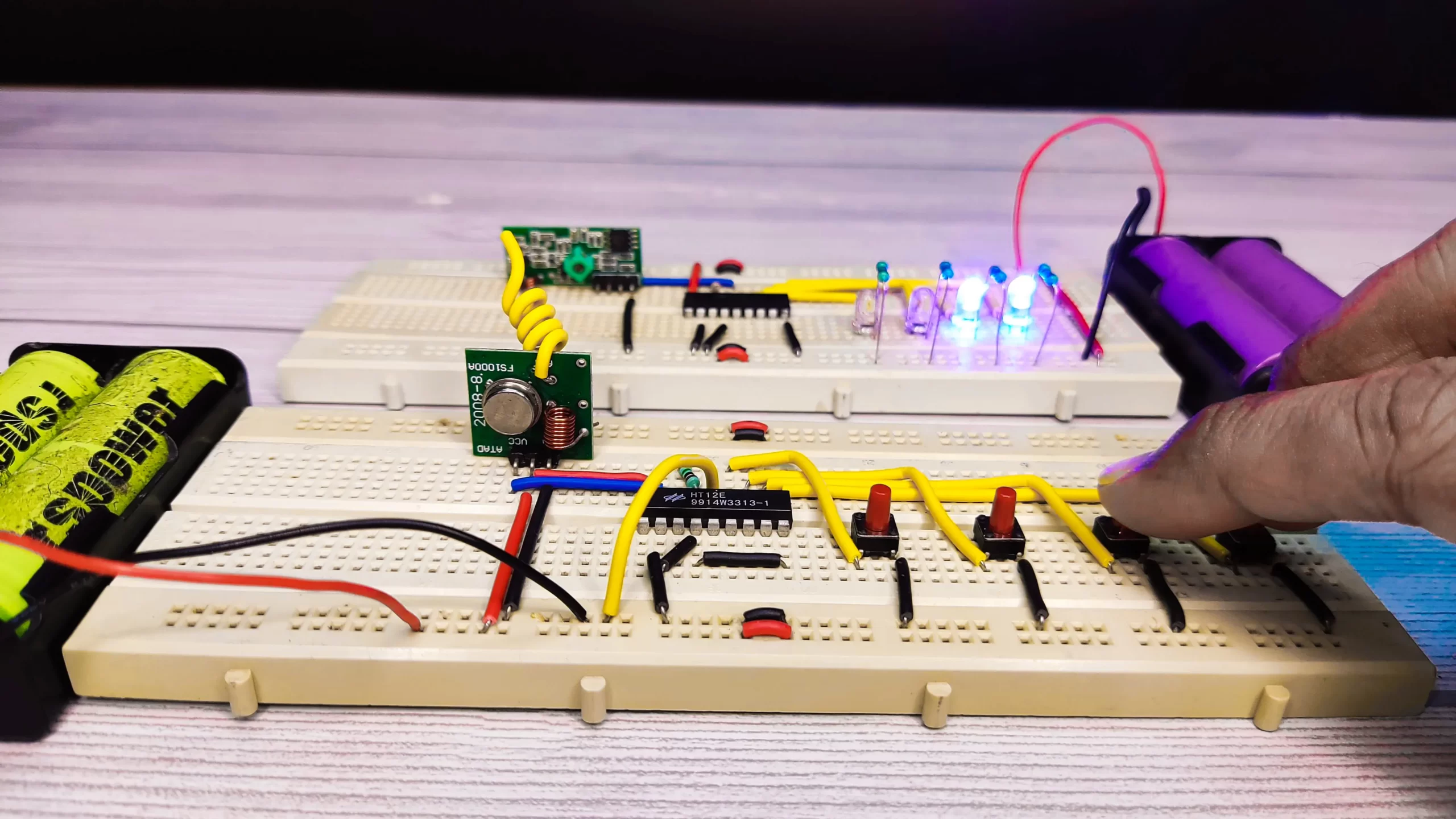
- Connect all the components as per the circuit diagram mentioned above and give a 5V power supply to both circuits.
- Initially, all the output LEDs will glow on the decoder part.
- Now press any button in the transmitter section, and we can observe that the corresponding LED will turn off at the decoder section.
- In the same way, for each switch at the transmitter section, the corresponding LED at the receiver section will also turn off. That’s how we can easily operate this FM Encoder/Decoder Circuit.
Advantages of FM Remote Encoder/Decoder Circuit
- For standalone operations
- LED indication of signal transmission
- Battery low indication
- Manchester modulation
- Sleep mode
Applications of FM Remote Encoder/Decoder Circuit
- According to RF communication, this circuit can be used in various short-range remote control applications.
- In some places, it is used as a burglar security system with some modifications.
- Also, it is used in door lock systems, garage opener systems, toy cars, etc.