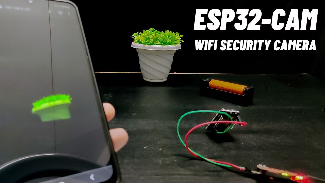
In this tutorial, we will learn how to build a wireless ESP32-CAM WiFi Security Camera which is very popular today to monitor our home, surrounding environment, office, shop, etc.
Even decent commercial WiFi Security Cameras aren’t also expensive, but they still cost quite a bit especially when you’re planning to buy several of them for a home security system. In this project, you will learn how to make your own DIY Surveillance Camera for under $10 depending on the supplies you used for clarification. This project will be based on the $8 ESP32-CAM AI thinker WiFi camera module, one of the best and cheapest camera development boards in the market.
With a unique IP address, you can directly log into the web server through your web browser, and view exactly what the camera sees. In future, we will add recording features as well (WiFi CCTV Camera with advanced controls). The security camera has some more features which will be discussed in another tutorial.
So without taking up any more time, let’s make this incredible project for our home.
Project

Circuit Diagram

Components Required
- ESP32-CAM Board
- FTDI USB to Serial Converter
- 5 Volt AC to DC Converter
- Connection Wire
- Container (Dummy CCTV Camera Kit)
Programming ESP32-CAM WiFi Security Camera
First, to program the ESP32-CAM module, first, connect the module to a USB-to-Serial FTDI converter as shown in the schematic below.

| ESP32-CAM | FTDI Module |
|---|---|
| U0R | TX |
| U0T | RX |
| GPIO0 | GND |
| +5V | +5V |
| GND | GND |

To program and be ready to upload the code to the ESP32-CAM module, connect GPIO pin 0 to the ground as mentioned above schematic. Also need to press the reset button to set it to flash mode before uploading the code.
Before uploading the code, make sure that you have the “https://dl.espressif.com/dl/package_esp32_index.json” link pasted into the preferences tab of the Arduino IDE. This link provides you access to example codes, libraries you need, etc.
Make sure your ESP32 board library version is at 2.0.2 or higher
Copy the whole Security Camera’s code from below and paste it into the Arduino IDE software. After that fill in all the necessary parameters such as selecting your camera model (uncomment “CAMERA_MODEL_AI_THINKER” if that’s your board and comment the unnecessary board type), and enter your WiFi credentials, and password.

Make sure you select “ESP32 Dev Module” with partition scheme “Minimal SPIFFS (1.9MB APP with OTA/190KB SPIFFS)”, enable PSRAM, and select your COM port. Then press upload. If any errors occur, then make sure that all the necessary libraries are installed.

When you start to see these connection dots on the debugging window as shown below, press the ESP32-CAM on-board reset button.

ESP32-CAM Code
#include "esp_camera.h"
#include <WiFi.h>
#include "esp_timer.h"
#include "img_converters.h"
#include "Arduino.h"
#include "fb_gfx.h"
#include "soc/soc.h" //disable brownout problems
#include "soc/rtc_cntl_reg.h"  //disable brownout problems
#include "esp_http_server.h"
//Replace with your network credentials
const char* ssid = "REPLACE_WITH_YOUR_SSID";
const char* password = "REPLACE_WITH_YOUR_PASSWORD";
#define PART_BOUNDARY "123456789000000000000987654321"
// This project was tested with the AI Thinker Model, M5STACK PSRAM Model and M5STACK WITHOUT PSRAM
#define CAMERA_MODEL_AI_THINKER
//#define CAMERA_MODEL_M5STACK_PSRAM
//#define CAMERA_MODEL_M5STACK_WITHOUT_PSRAM
// Not tested with this model
//#define CAMERA_MODEL_WROVER_KIT
#if defined(CAMERA_MODEL_WROVER_KIT)
#define PWDN_GPIO_NUM    -1
#define RESET_GPIO_NUM   -1
#define XCLK_GPIO_NUM    21
#define SIOD_GPIO_NUM    26
#define SIOC_GPIO_NUM    27
#define Y9_GPIO_NUM      35
#define Y8_GPIO_NUM      34
#define Y7_GPIO_NUM      39
#define Y6_GPIO_NUM      36
#define Y5_GPIO_NUM      19
#define Y4_GPIO_NUM      18
#define Y3_GPIO_NUM       5
#define Y2_GPIO_NUM       4
#define VSYNC_GPIO_NUM   25
#define HREF_GPIO_NUM    23
#define PCLK_GPIO_NUM    22
#elif defined(CAMERA_MODEL_M5STACK_PSRAM)
#define PWDN_GPIO_NUM     -1
#define RESET_GPIO_NUM    15
#define XCLK_GPIO_NUM     27
#define SIOD_GPIO_NUM     25
#define SIOC_GPIO_NUM     23
#define Y9_GPIO_NUM       19
#define Y8_GPIO_NUM       36
#define Y7_GPIO_NUM       18
#define Y6_GPIO_NUM       39
#define Y5_GPIO_NUM        5
#define Y4_GPIO_NUM       34
#define Y3_GPIO_NUM       35
#define Y2_GPIO_NUM       32
#define VSYNC_GPIO_NUM    22
#define HREF_GPIO_NUM     26
#define PCLK_GPIO_NUM     21
#elif defined(CAMERA_MODEL_M5STACK_WITHOUT_PSRAM)
#define PWDN_GPIO_NUM     -1
#define RESET_GPIO_NUM    15
#define XCLK_GPIO_NUM     27
#define SIOD_GPIO_NUM     25
#define SIOC_GPIO_NUM     23
#define Y9_GPIO_NUM       19
#define Y8_GPIO_NUM       36
#define Y7_GPIO_NUM       18
#define Y6_GPIO_NUM       39
#define Y5_GPIO_NUM        5
#define Y4_GPIO_NUM       34
#define Y3_GPIO_NUM       35
#define Y2_GPIO_NUM       17
#define VSYNC_GPIO_NUM    22
#define HREF_GPIO_NUM     26
#define PCLK_GPIO_NUM     21
#elif defined(CAMERA_MODEL_AI_THINKER)
#define PWDN_GPIO_NUM     32
#define RESET_GPIO_NUM    -1
#define XCLK_GPIO_NUM      0
#define SIOD_GPIO_NUM     26
#define SIOC_GPIO_NUM     27
#define Y9_GPIO_NUM       35
#define Y8_GPIO_NUM       34
#define Y7_GPIO_NUM       39
#define Y6_GPIO_NUM       36
#define Y5_GPIO_NUM       21
#define Y4_GPIO_NUM       19
#define Y3_GPIO_NUM       18
#define Y2_GPIO_NUM        5
#define VSYNC_GPIO_NUM    25
#define HREF_GPIO_NUM     23
#define PCLK_GPIO_NUM     22
#else
#error "Camera model not selected"
#endif
static const char* _STREAM_CONTENT_TYPE = "multipart/x-mixed-replace;boundary=" PART_BOUNDARY;
static const char* _STREAM_BOUNDARY = "\r\n--" PART_BOUNDARY "\r\n";
static const char* _STREAM_PART = "Content-Type: image/jpeg\r\nContent-Length: %u\r\n\r\n";
httpd_handle_t stream_httpd = NULL;
static esp_err_t stream_handler(httpd_req_t *req) {
  camera_fb_t * fb = NULL;
  esp_err_t res = ESP_OK;
  size_t _jpg_buf_len = 0;
  uint8_t * _jpg_buf = NULL;
  char * part_buf[64];
  res = httpd_resp_set_type(req, _STREAM_CONTENT_TYPE);
  if (res != ESP_OK) {
    return res;
  }
  while (true) {
    fb = esp_camera_fb_get();
    if (!fb) {
      Serial.println("Camera capture failed");
      res = ESP_FAIL;
    } else {
      if (fb->width > 400) {
        if (fb->format != PIXFORMAT_JPEG) {
          bool jpeg_converted = frame2jpg(fb, 80, &_jpg_buf, &_jpg_buf_len);
          esp_camera_fb_return(fb);
          fb = NULL;
          if (!jpeg_converted) {
            Serial.println("JPEG compression failed");
            res = ESP_FAIL;
          }
        } else {
          _jpg_buf_len = fb->len;
          _jpg_buf = fb->buf;
        }
      }
    }
    if (res == ESP_OK) {
      size_t hlen = snprintf((char *)part_buf, 64, _STREAM_PART, _jpg_buf_len);
      res = httpd_resp_send_chunk(req, (const char *)part_buf, hlen);
    }
    if (res == ESP_OK) {
      res = httpd_resp_send_chunk(req, (const char *)_jpg_buf, _jpg_buf_len);
    }
    if (res == ESP_OK) {
      res = httpd_resp_send_chunk(req, _STREAM_BOUNDARY, strlen(_STREAM_BOUNDARY));
    }
    if (fb) {
      esp_camera_fb_return(fb);
      fb = NULL;
      _jpg_buf = NULL;
    } else if (_jpg_buf) {
      free(_jpg_buf);
      _jpg_buf = NULL;
    }
    if (res != ESP_OK) {
      break;
    }
    //Serial.printf("MJPG: %uB\n",(uint32_t)(_jpg_buf_len));
  }
  return res;
}
void startCameraServer() {
  httpd_config_t config = HTTPD_DEFAULT_CONFIG();
  config.server_port = 80;
  httpd_uri_t index_uri = {
    .uri       = "/",
    .method    = HTTP_GET,
    .handler   = stream_handler,
    .user_ctx  = NULL
  };
  //Serial.printf("Starting web server on port: '%d'\n", config.server_port);
  if (httpd_start(&stream_httpd, &config) == ESP_OK) {
    httpd_register_uri_handler(stream_httpd, &index_uri);
  }
}
void setup() {
  WRITE_PERI_REG(RTC_CNTL_BROWN_OUT_REG, 0); //disable brownout detector
  Serial.begin(115200);
  Serial.setDebugOutput(false);
  camera_config_t config;
  config.ledc_channel = LEDC_CHANNEL_0;
  config.ledc_timer = LEDC_TIMER_0;
  config.pin_d0 = Y2_GPIO_NUM;
  config.pin_d1 = Y3_GPIO_NUM;
  config.pin_d2 = Y4_GPIO_NUM;
  config.pin_d3 = Y5_GPIO_NUM;
  config.pin_d4 = Y6_GPIO_NUM;
  config.pin_d5 = Y7_GPIO_NUM;
  config.pin_d6 = Y8_GPIO_NUM;
  config.pin_d7 = Y9_GPIO_NUM;
  config.pin_xclk = XCLK_GPIO_NUM;
  config.pin_pclk = PCLK_GPIO_NUM;
  config.pin_vsync = VSYNC_GPIO_NUM;
  config.pin_href = HREF_GPIO_NUM;
  config.pin_sscb_sda = SIOD_GPIO_NUM;
  config.pin_sscb_scl = SIOC_GPIO_NUM;
  config.pin_pwdn = PWDN_GPIO_NUM;
  config.pin_reset = RESET_GPIO_NUM;
  config.xclk_freq_hz = 20000000;
  config.pixel_format = PIXFORMAT_JPEG;
  if (psramFound()) {
    config.frame_size = FRAMESIZE_UXGA;
    config.jpeg_quality = 10;
    config.fb_count = 2;
  } else {
    config.frame_size = FRAMESIZE_SVGA;
    config.jpeg_quality = 12;
    config.fb_count = 1;
  }
  // Camera init
  esp_err_t err = esp_camera_init(&config);
  if (err != ESP_OK) {
    Serial.printf("Camera init failed with error 0x%x", err);
    return;
  }
  // Wi-Fi connection
  WiFi.begin(ssid, password);
  while (WiFi.status() != WL_CONNECTED) {
    delay(500);
    Serial.print(".");
  }
  Serial.println("");
  Serial.println("WiFi connected");
  Serial.print("Camera Stream Ready! Go to: http://");
  Serial.print(WiFi.localIP());
  // Start streaming web server
  startCameraServer();
}
void loop() {
  delay(1);
}Make sure to unplug the wire between IO0 and GND and press the reset button. Then insert a Micro SD card into the SD card slot (Min 4GB), then obtain a unique IP address from the Arduino IDE serial monitor.
Preparing ESP32-CAM and Getting IP Address

Troubleshooting of ESP32-CAM Security Camera
- Failed to connect to ESP32: Timed out waiting for packet header
- Camera init fell with error 0x20001 or similar
- Brownout detector or Guru meditation error
- Sketch too big error – Wrong partition scheme selected
- Board at COMX is not available – COM Port Not Selected
- Psram error: GPIO isr service is not installed
- Weak Wi-Fi Signal
- No IP Address in Arduino IDE Serial Monitor
- Can’t open web server
- The image lags/shows lots of latency