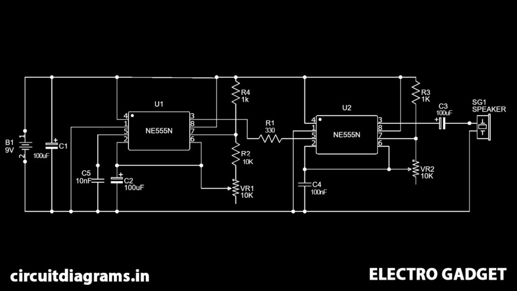
These days, the calling bell is basic in each house. We, every day watch various sorts of calling bells accessible in the market and they produce various kinds of music relying upon their usefulness. One can structure their own calling bell ringer utilizing simple electronic parts. So this time we have chosen to make a calling bell circuit with a Ding Dong sound by utilizing 555 timer clocks.
Must Read 555 Timer Projects
Principle Behind This Calling Bell Circuit
This circuit chiefly comprises two 555 timer clock ICs. First IC is worked in astable mode and the frequency of the second IC is tweaked by the first IC. For that, the output pin of the first IC is associated with the fifth pin of the second IC. The first IC is worked at a frequency of 1Hz. The 555 timer clock IC can be worked at the required frequency by tuning the RC circuit. In astable mode, no outer activating is required. This has no steady state.
Circuit Diagram
Components Required
- 555 Timer
- Resistors (330Ω, 2KΩ, 10KΩ)
- 50 KΩ Potentiometer
- 100uF/25V Capacitor
- Capacitor 100nF, 10nF
- LED
- 9V Battery
- Push-button
- Speaker
- Breadboard
Circuit Connection
Here we have utilized two separate 555 timer clock ICs to deliver the required ding-dong sound frequency. In 555 timer IC1, we have associated a 1KΩ resistor between Vcc and pin seventh of the 555 timers.
Also, a 10KΩ resistor and 50 KΩ Pot between pin 7 and pin 6. Pin 2 is shorted with pin 6 and a 100uF/25V capacitor is associated with pin 2 or pin 6 for ground. A 10nF capacitor is additionally associated with pin 5 of the first IC1 regarding the ground.
Pin 1 is associated with ground and pins 4 and 8 are associated with Vcc. The output pin 3 of 555 timer IC1 is associated with pin 5 of 555 timer IC2 through 330Ω.
In the second 555 timer IC2, pin 4 and pin 8 are associated with Vcc and pin 1 to ground. A 100nF capacitor is associated with pin 2 or pin 6 with regard to the ground. A 1KΩ resistor is additionally associated with Vcc and the seventh of IC2.
Also, another 50 KΩ Pot is associated between pin 7 and pin 6. A speaker is associated with pin 3 of IC2 through a 100uF/25V capacitor for ground.
A 100uF/25V capacitor is additionally associated with Vcc and ground. At last, we have associated a 9V battery to control the circuit.
Working Principle of Calling Bell Circuit
In this calling bell circuit, we have arranged a 555 timer IC in an astable multivibrator mode. Here we have made two astable multivibrators, for two 555 ICs, which are designed at various frequencies and frequencies can be balanced by utilizing connected potentiometers.
The initial 555 timer multivibrator is producing around 1 Hz frequency which is the time period and dong tone. The output of the first astable multivibrator IC1 is applied to the second astable multivibrator through pin 5 of the second 555 timer clock IC2.
The second multivibrator balances it over its sign and produces a distinctive sound on the speaker associated with output pin 3 of the second 555 IC2. RV1 is answerable for setting ding dong sound time span and RV2 is liable for the change in a sound.
