For this time, we are going to build a car speed detector circuit using Arduino and IR sensors. You can check the speed of a moving car. We know many rules we have to follow while driving a car. The most common rule is to maintain speed on certain roads. If we violate these rules, we get fined or punished in other ways.
There are many cars and other vehicles in the traffic. A human can’t detect the speed of all vehicles. So traffic officers depend on a handheld gun. This gun works on radar technology. This can manually check speed but for many vehicles, it may fail.
From there the thought arises, how to make this automatic. So we build this automatic speed detection by Arduino. Now you just need to place this project in a fixed place. This system automatically take values and send data without any human intervention. Before going to build this project, first, check out how we can make a DIY Infrared Sensor.
Principle of Car Speed Detector using Arduino
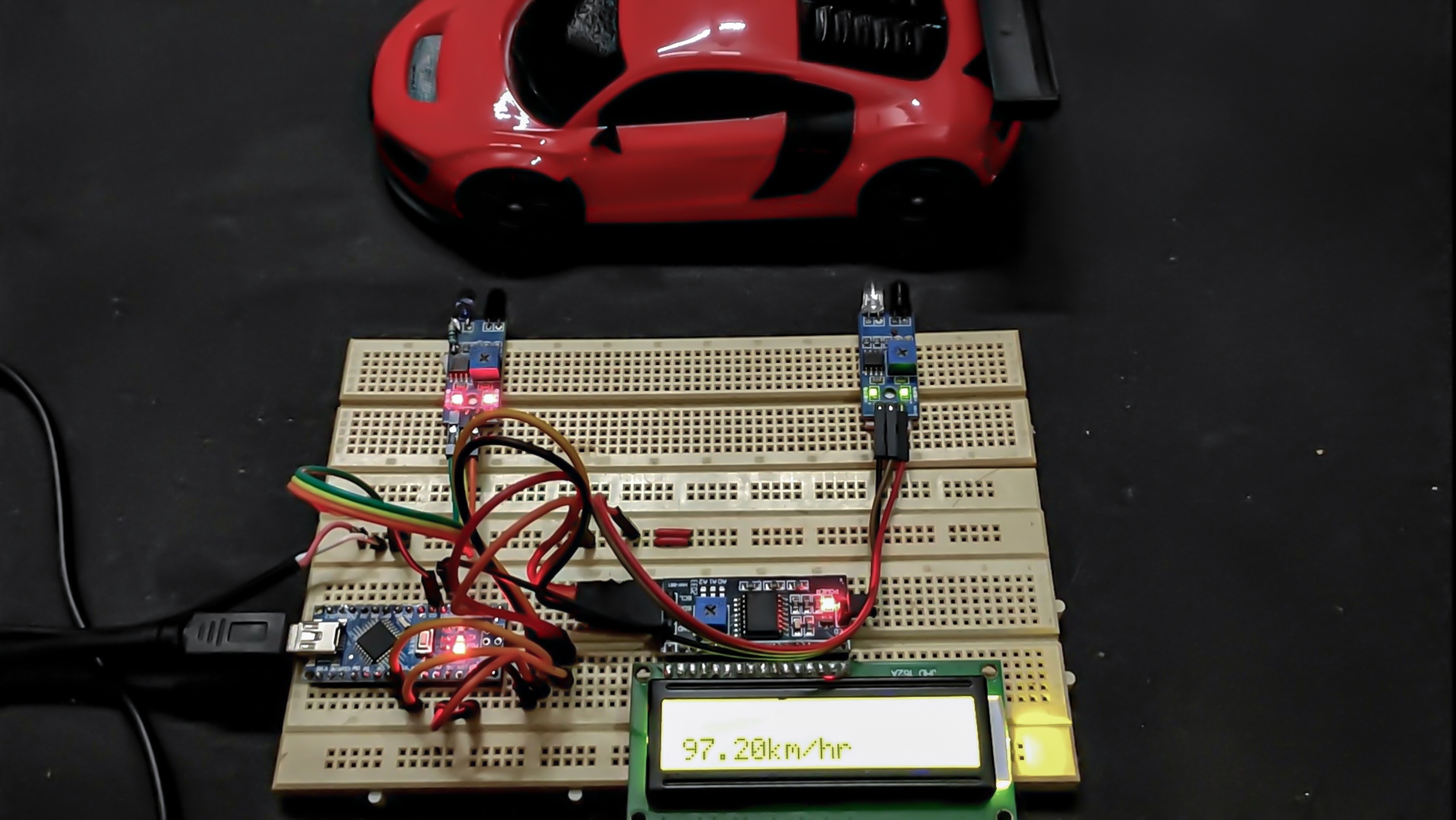
The main parts of this project are Arduino and IR sensors. These sensors can detect the speed of a vehicle. In this project, we use two reflective type IR sensors. These two sensors are placed 10 cm apart.
When a car passes the first sensor, this project starts working. It measures time until the car passes the second one. By this process, it takes data of the movement of the car.
By this value, you can simulate between two sensors to be 5 meters. You can calculate the speed at which the vehicle travelled between those sensors.
All the data and calculations can be done by Arduino and the value is shown in the LCD module.
Project

Circuit Diagram

Components Required
- Arduino
- IR Module (x2)
- 16×2 LCD Display Module
- 10KΩ Variable Resistor
- 1KΩ Resistor
- 5V Power Supply
Components Required For DIY IR Sensor/PCB
- IR Transmitter (x2)
- IR Receiver (x2)
- LM358 IC (x2)
- 10KΩ Variable Resistor (x2)
- 1KΩ Resistor (x4)
- Hi-Link 5V
Circuit Design of Car Speed Detector
The circuit design is very simple for this project. The first IR sensor’s digital out is connected to pin 11 and the second IR sensor is connected to pin 12 of the Arduino. The voltage is provided for both sensors.
To see the speed detected by sensors, we used a 16×2 LCD. Its data pins D4, D5, D6, D7 are connected to digital I/O pins of the Arduino D5, D4, D3, D2 respectively. The RS and E pins of the LCD are connected to pin D7 and D6 of the Arduino.
How to Operate Car Speed Detector?
- At first complete the circuit as mentioned in the diagram and upload the code in Arduino.
- Place IR sensors at the edges of the breadboard. So the distance between them is nearly 10 cm. Now power up the circuit.
Then move your hand or any moveable thing in front of the sensors. - At last check the result on the LCD display.
Working of Car Speed Detector Using Arduino
The working of this project is not much difficult. The Arduino continuously get data from the sensors. When the car or any moveable thing passes the first IR sensor it gets alert. After it, Arduino captures a timestamp at this moment.
Then the second IR sensor’s working is started. It sends data to Arduino when the car passes it. Here we used the Millis() function of Arduino to capture the timestamps.
Now Arduino calculates the velocity by assuming the distance is 5 meters. Then send the value to an LCD. The LCD shows the result in kilometres per hour.
Applications of Car Speed Detector
- It automatically captures speed without any human.
- With this project you count how many number of cars passes on this day.
- Also it can be used as a traffic logger or traffic counter.
Arduino Code Without I2C Module
#include <LiquidCrystal.h>
const int rs = 7, en = 6, d4 = 5, d5 = 4, d6 = 3, d7 = 2;
LiquidCrystal lcd(rs, en, d4, d5, d6, d7);
int s1 = 2;
int s2 = 3;
int Time1;
int Time2;
int Time;
int flag = 0;
int distance = 27;
float Speed;
float s;
void setup() {
  attachInterrupt(0,fun1,RISING);
  attachInterrupt(1,fun2,FALLING);
  lcd.begin(16, 2);
  lcd.clear();
  lcd.print("Speed Detector  ");
  delay(2000);
  lcd.clear();
}
void fun1()
{
  Time1 = millis();
  if (flag == 0) {flag = 1;}
  else {flag = 0;}
}
void fun2()
{
  Time2 = millis();
  if (flag == 0) {flag = 1;}
  else {flag = 0;}
}
void loop() {
  if (flag == 0)
  {
  if      (Time1 > Time2) {Time = Time1 - Time2;  Speed = (distance*1000)/Time;}

  else if (Time2 > Time1) {Time = Time2 - Time1;  Speed = (distance*1000)/Time;}

  else    {Speed = 0;}
  }

  if (Speed == 0) {
    lcd.setCursor(0, 0);
    lcd.print("Detecting...");
    lcd.clear();
    }
  else {
    s = Speed*0.036;  // from cm/sec to km/hr
    lcd.setCursor(0, 1);
    lcd.print(s);
    lcd.print("km/hr");
    delay(1000);
    Time1 = 0;
    Time2 = 0;
    }
}
Arduino Code With I2C Module
#include<LiquidCrystal.h>
#include <Wire.h>
#include <LiquidCrystal_I2C.h>
LiquidCrystal_I2C lcd(0x27, 16, 2);
int s1 = 2;
int s2 = 3;
int Time1;
int Time2;
int Time;
int flag = 0;
int distance = 27;
float Speed;
float s;
void setup() {
  attachInterrupt(0,fun1,RISING);
  attachInterrupt(1,fun2,FALLING);
  lcd.init();
  lcd.backlight();
  lcd.clear();
  lcd.print("Speed Detector  ");
  delay(2000);
  lcd.clear();
}
void fun1()
{
  Time1 = millis();
  if (flag == 0) {flag = 1;}
  else {flag = 0;}
}
void fun2()
{
  Time2 = millis();
  if (flag == 0) {flag = 1;}
  else {flag = 0;}
}
void loop() {
  if (flag == 0)
  {
  if      (Time1 > Time2) {Time = Time1 - Time2;  Speed = (distance*1000)/Time;}

  else if (Time2 > Time1) {Time = Time2 - Time1;  Speed = (distance*1000)/Time;}

  else    {Speed = 0;}
  }

  if (Speed == 0) {
    lcd.setCursor(0, 0);
    lcd.print("Detecting...");
    lcd.clear();
    }
  else {
    s = Speed*0.036;  // from cm/sec to km/hr
    lcd.setCursor(0, 1);
    lcd.print(s);
    lcd.print("km/hr");
    delay(1000);
    Time1 = 0;
    Time2 = 0;
    }
}


