When you are in direct need of measuring the inductance but you got no multimeter or not even an oscilloscope to do that, here we got you covered, as we are going to build a very cheap and easy Inductance Meter by utilising the Arduino microcontroller. The procedure is accurate with a scope from 80uH to 30000uH, but it should be working for much larger or a bit small inductors. Also, we made a Capacitance Meter Using Arduino in a previous article.
Project

Circuit Diagram

Components Required
- Arduino Nano
- 16×2 LCD Display
- I2C LCD Display
- LM339 Comparator IC
- 1uF Non-Polar Capacitor (x2)
- Resistor (150Ω, 330Ω)
- 1N4007 PN Diode
- Connection Wire
- Breadboard
- 5V Power Supply
About LM339 Comparator IC
Microcontrollers can’t precisely analyse Analog signals. The Atmega328 ADC is capable of sampling Analog signals at 9600hz or 1ms, which is fast but not enough for the project. So we have to use the chip that’s capable of turning real-world signals into basic digital signals, the LM339 comparator which switches faster than a normal LM741 op-amp.
What is an LC Circuit?
An inductor parallelly set with a capacitor is called an LC circuit, it will make a sound like a ringing bell. It doesn’t matter what frequency is used or how hard a bell is struck, it will still ring at its certain resonating frequency. We will strike the LC bell electronically, wait it out to make the things resonate, and then measure it. Some internal resistance is observed, so it’s confirmed as an RLC circuit
After that, as the voltage on the LC circuit becomes positive, the LM339 will float, which can be raised high up using a pull-up resistor. As the voltage on the LC circuit become negative, the LM339 will put its output to the ground.
We will then apply a pulse signal to the LC circuit. We will use 5 volts from the Arduino. Then we can change the voltage from 5 volts to 0 volts directly. This change will make the circuit resonate and create a cushioned sinusoidal signal that oscillates at the resonant frequency. Then what we need to do is to measure that frequency. And we will later use that to get the inductance value, Arduino will be used to measure the frequency and calculate the value.

we could get the value of L because we know the frequency F that we’ve just measured and we also know the values of the capacitor C because it’s a component that we’ve selected. All we need is to obtain L from this equation.

The wave here is a true sinusoidal wave, it spends equal time above zero volts and below zero volts. This means that the comparator will turn it into a square wave with a duty of 50%, and pulse In(pin, HIGH, 5000); will measure the time in microseconds elapsed rising edge to the falling edge. This measurement can be doubled to get the period and the inverse of the period is the frequency. As the circuit is resonating, this frequency is the resonating frequency.
As this is an RLC circuit and as it got internal resistance, it won’t be able to change any characteristics of the resonating frequency. The RLC can still resonate but the amplitude will end. If the resistance is low the RLC will tend to latch onto the precise resonating frequency more quickly.
Working Principle of Arduino Based Inductance Meter
Here in the Inductance Meter, we apply a 5 volts pulse on the LC circuit using Arduino digital pin D13 for some time. After that, the pulse is stopped and the circuit will start to resonate. The comparator will give a square signal output with the same frequency that the Arduino will measure by using the pulse in function as it measures the time between each pulse of the square wave. After that, it will calculate the value and print it on the LCD screen.
Now We have to apply 5 volts to the LM339 comparator. Then connect ground to pin 12 of the LM339 and 5 volts to pin 3. Comparator input pin 2 will be used here. The negative input will be pin 6 of the LM339 and the positive pin 7. The output is pin 1 which is the pin marked with a black dot. The pin number increases counterclockwise. Connect the comparator output to the pin D11 of the Arduino. Connect the pin D13 from the microcontroller through a 150 ohms resistor and a diode to the LC circuit. Input the next code and we are good to go.
Arduino Code
To compile this code you need to install the LiquidCrystal_I2C.h library first.
#include <Wire.h>
#include <LiquidCrystal_I2C.h>
LiquidCrystal_I2C lcd(0x27,20,4); //If the LCD address is not 0x27. Change to 0x3f
//D13 is the input to the circuit. Connects with 150ohm resistor
double pulse, frequency, capacitance, inductance;
void setup()
{
lcd.init();
lcd.backlight();
pinMode(11, INPUT);
pinMode(13, OUTPUT);
delay(200);
}
void loop()
{
digitalWrite(13, HIGH);
delay(5); //Time to charge inductor
digitalWrite(13,LOW);
delayMicroseconds(100); //Make sure resination is measured
pulse = pulseIn(11,HIGH,5000); //Returns 0 if timeout
if(pulse > 0.1)
{
capacitance = 2.E-6; // - insert value here
frequency = 1.E6/(2*pulse);
inductance = 1./(capacitance*frequency*frequency*4.*3.14159*3.14159);
inductance *= 1E6; //Note that this is the same as saying inductance = inductance*1E6
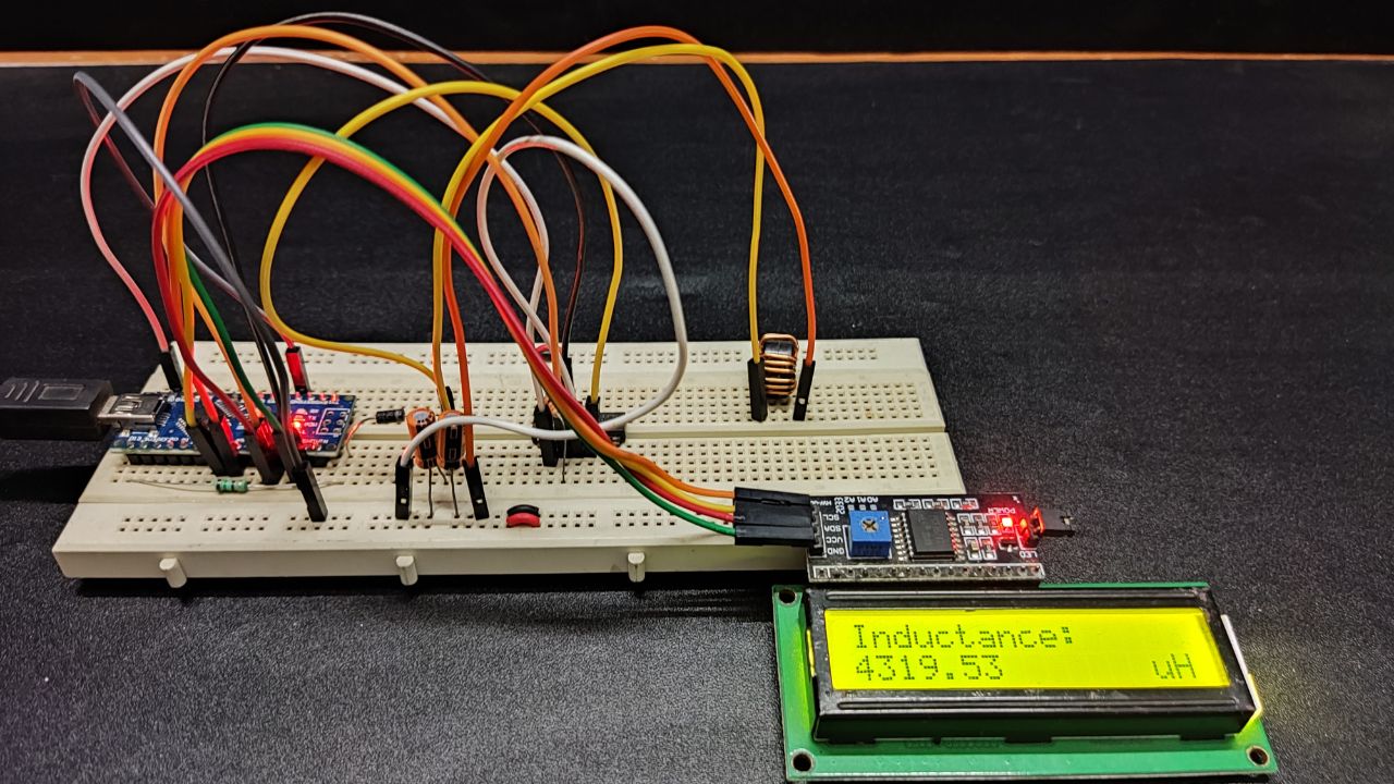
lcd.clear();
lcd.setCursor(0,0);
lcd.print("Inductance:");
lcd.setCursor(0,1);
lcd.print(inductance);
lcd.setCursor(14,1);
lcd.print("uH");
delay(10);
}
}


