The 555 Timer IC is one of the most popular and most frequently used integrated circuits. It performs an array of timing tasks in the electronic circuits and there is a huge list of experiments that can be performed with 555 IC. That is why it is very popular for electronics hobbyists.
Must Read 555 Timer Projects
But before using this IC, you should check whether it is working or not. So, in this project, We are going to learn how a simple IC testing circuit is built that can be used as a 555 Timer IC Testing Circuit and determine whether the 555 IC is working or not.
Brief Description About 555 Timer IC
Before going to build this project, a few important things you need to know before understanding how the 555 Timer IC testing circuit works. The first thing is that the 555 IC is available in an 8-pin dual-in-line package (DIP).
While the second one about 555 Timer IC is that it has three modes of operation: Astable, Monostable and Bistable. The circuit implemented in this project is basically an Astable Mode of operation of the 555 Timer IC.
Must Read 555 Timer Full Tutorial
Principle Behind 555 Timer IC
This simple 555 IC testing circuit can be used to test your 555 timer IC. So, before implementing your 555 IC in any project, make sure that your IC is good or bad. This can be done by configuring the IC to act as an oscillator i.e. 555 is configured in Astable mode of operation.
The 555 tester circuit will rapidly tell you if the timer is functioning or not. An important feature of this circuit is it will tell whether the 555 Timer is shorted or it is not oscillating.
Project

Circuit Diagram

Components Required
- 555 IC (Which Under Test)
- 8 Pin IC Holder
- 10KΩ Resistor
- 1KΩ Resistor
- 47μF/25V Capacitor
- 0.01μF Capacitor
- LEDs
- 12V Power Supply
- Connecting Wires
- Breadboard
Circuit Connection
As mentioned earlier, I am going to use the 555 IC in its Astable Mode of operation. If you are familiar with this mode, then let’s start to build this circuit connection.
At first, connect pin 4 and pin 8 to +12V Supply and pin 1 to ground. Short pins 2 and 6. Now, connect a 10KΩ resistor between VCC and pin 7. This resistor will be called R1.
Also, connect another 10KΩ resistor between pin 7 and pin 6. This resistor will be called R2. A 47μF/25V capacitor is connected between pin 6 and ground.
An optional connection is to connect a 0.01μF capacitor between pin 5 and ground. Finally, connect two LEDs as shown in the circuit diagram to pin 3 of the IC.
How to Check the 555 Timer IC?
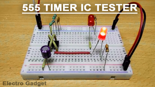
First of all, insert the IC in the socket very carefully so that no pin of the 555 timer gets damaged. Now to see the result, switch on the power supply. If your ic is working properly, then both the LEDs (Red LED) will glow alternately. If any of the LEDs are off or both the LEDs are not glowing, it means that your 555 timer IC is damaged.
Working of 555 Timer IC Tester Circuit
In this circuit, I have used the 555 IC as an Astable multivibrator and when power is provided to the circuit, the LEDs will start blinking, which means that the IC is working. The blinking rate of LEDs can be changed by increasing or decreasing the values of resistors R1 and R2 and capacitor C1.
You can calculate the time duration with the help of a formula.
ON Time (HIGH) in Seconds = 0.693 * (R1 + R2) * C1
OFF Time (LOW) in Seconds = 0.693 * R2 * C1
Total Time Period in Seconds = 0.693 * (R1 +2R2)*C1
Frequency = 1.44 / ((R1 + 2R2) * C1)
If you substitute these values in the above equations, you will get the following results.
Frequency = 1.023 Hertz
ON Time = 0.651 Seconds
OFF Time = 0.326 Seconds
Time Period = 0.977 Seconds
As soon as the power supply is supplied, C1 will start charging through R1 and R2. When the voltage across C1 rises above 2/3 of the supply voltage, the internal flip-flop toggles. As a result, pin 7 becomes low and C1 starts to discharge.
When the voltage across C1 goes below 1/3 of the supply voltage, the internal flip-flop resets and pin 7 goes high. The C1 then starts to charge again. It indicates that your IC is in good condition. Based on the charging and discharging times of the Capacitor, the output will stay HIGH or LOW and the LEDs will flash accordingly. From these observations, we can conclude that the 555 Timer IC is good or not.


